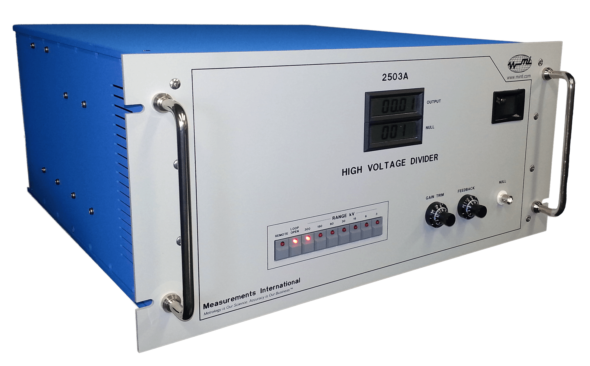
The 2500A, 2501A, 2502A and 2503A complete the low-voltage arm of a high-voltage capacitive divider. Based on the compensated-current-comparator it provides ultra-precise ratio division of high AC voltages down to measurable levels. The output of the divider can be read by an AC/DC transfer device for precision measurements of the input voltage or by a precision power analyzer such as the MI 2020A for direct measurements of transformer or reactor losses under control of the IEEE-488 interface.
Model 2500A: The input current comes from a high voltage applied to a low-loss high-voltage capacitor (100 pF for 120 kV, 50 pF for 240 kV). Seven gain stages (1, 2, 5, 10, 20, 50, 100) provide flexibility across voltage ranges. At gain 1, full-scale input reaches 120 kV; at gain 100, it drops to 1200 V. Full-scale output is 120 V for 120 kV input with 10% overrange. For 240 kV input using a 50 pF capacitor, full-scale input spans 240 kV (gain 1) to 2400 V (gain 100), with 120 V full-scale output and 10% overrange.
Model 2501A: The 2501A accepts inputs up to 2400 Vac using a 1,000 pF standard capacitor. At gain 1, full-scale input is 2400 V; at gain 100, it is 120 V. Full-scale output is 120 V for all ranges.
Model 2502A: The 2502A accepts 480 kV with a 100 pF capacitor, or 960 kV with a 50 pF capacitor. Seven gain stages provide flexibility across ranges. With the 100 pF capacitor, gain 1 yields 480 kV full-scale input and gain 100 yields 4,800 V; full-scale output is 120 V. With the 50 pF capacitor, gain 1 yields 960 kV and gain 100 yields 9.6 kV.
Model 2503A: The 2503A accepts 300 kV with a 50 pF capacitor or 150 kV with a 100 pF capacitor. Seven gain stages provide flexibility. With the 50 pF capacitor, gain 1 yields 300 kV and gain 100 yields 3.0 kV with 10% overrange. With the 100 pF capacitor, gain 1 yields 150 kV and gain 100 yields 1.5 kV. Full-scale output is 100 V for all ranges.
Each unit includes a 1000 pF low-loss standard reference capacitor. Optional high-voltage capacitors (1000 pF to 800 kV) are available for the divider input.
Operating Principle: A simplified schematic of the current comparator-based voltage divider is shown in Figure 1. The current in the low-loss high-voltage capacitor (CH) is compared, using the current comparator, with the current obtained by applying the output voltage VL to a stable low-loss standard capacitor (CL).
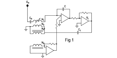
Due to the magnitude and phase errors of EL, the current comparator will not be in ampere-turn balance. The difference in current, derived from the output of the detection winding ND, is added through the feedback circuit to the current in the solid dielectric capacitor Cf resulting in a highly accurate and self-balancing voltage at VL. Thus the feedback circuit is used to provide an ampere-turn balance in the current comparator to correct the magnitude and phase errors of the output voltage VL.
The output voltage VL of the current comparator based divider is given by:
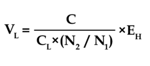
From the above equation, the capacitance ratio of CH and CL and the current comparator-winding ratio determine the divider output. Several gain stages are provided to ensure that the output voltage is always operated at near or full-scale. To change the gain on the high-voltage divider, a decrease in the current-comparator-winding ratio (N2/N1) is required to maintain an ampere-turn balance. Relays, which are used to change the electronic gain and winding ratio are driven simultaneously to keep the winding ratio times the gain constant. The gain of the divider is set, as 1, 2, 5, 10, 20, 50, 100 where 1 corresponds to a voltage at VH of 100 kV, 200 kV on the 2500A, 480 kV or 960 kV on the 2502A and 300 kV or 150 kV on the 2503A. Gain 100 would represent an input voltage at VH of 1 kV, 2 kV, 5 kV and 10 kV respectively. The uncertainty of the high-voltage divider is equal to the uncertainty associated with the two-stage-current transformer and the uncertainty of CH and CL. On the 2503A gain, 100 would represent an input voltage at VH of 3 kV and 1.5 kV.
Low-Loss Capacitor and Feedback Capacitor
For zero temperature coefficient operation, the divider depends on the stability and accuracy of the low-loss standard capacitor (CL) and feedback circuit gain. Capacitor CL is a 1,000 pF low-loss standard capacitor with dissipation and magnitude errors under a few ppm and a temperature coefficient of a few ppm. The values of CL and Cf produce a nominal output voltage of 100 V across all units.
Current Comparator
The 2-stage compensated current comparator uses variable turns N1 and fixed turns N2. A compensation winding (N3) parallels N2 with equal turns to reduce leakage impedance. The detection winding (ND) connects to a current-to-voltage converter, producing a voltage proportional to and in phase with unbalanced ampere-turns in the comparator.
Feedback Circuit
The feedback circuit gain (approximately 100) corrects for dissipation factor and capacitance variation in the solid dielectric feedback capacitor (Cf). The circuit operates at 100% feedback.
All models offer front panel and IEEE-488 control. Two LCDs monitor internal test voltages and divider output. The instrument mounts in a rack-mounted enclosure with full transient protection. All connections are on the rear.
Loop Gain Check
The divider operates in Open-Loop or Closed-Loop modes. To verify loop gain and current comparator feedback function, introduce an error using the front-panel Gain Trim potentiometer and Null Indicator. In Open-Loop mode, adjust the potentiometer to minimize error; a 500 ppm introduced error typically reduces to ~5 ppm when the loop closes. During operation, the divider always runs in Closed-Loop mode.
Applications
1. Reactor Loss Measurement Systems
2. Transformer Loss Measurement Systems
3. AC High-Voltage Measurement Systems
4. Power Calibration Systems
2500A
| Input Capacitor 100 pF | Input Voltage: 120, 60, 24, 12, 6, 2.4, 1.2 kV |
| Output Voltage: 120 V | |
| Input Capacitor 50 pF | Input Voltage: 240, 120, 48, 24, 12, 4.8, 2.4 kV |
| Output Voltage: 120 V |
2501A
| Input Capacitor 1000 pF | Input Voltage: 2400, 1200, 600, 480, 360, 240, 120 V |
| Output Voltage: 120 V |
2502A
| Input Capacitor 50 pF | Input Voltage: 480, 240, 96, 48, 19.2, 9.6, 4.8 kV |
| Output Voltage: 120 V | |
| Input Capacitor 50 pF | Input Voltage: 960, 480, 192, 96, 38.4, 19.2, 9.6 kV |
| Output Voltage: 120 |
2503A
| Input Capacitor 50 pF | Input Voltage: 300, 150, 60, 30, 15, 6, 3 kV |
| Output Voltage: 100 V |
General
| Maximum Primary Output Voltage | 120 Vac RMS with 10 % overrange |
| Division Ratio Uncertainty | Magnitude < 20 ppm Quadrature < 20 ppm |
| Frequency Range of Measured Values | 40 Hz to 400 Hz |
| Gain Selection | 7 Gain Setting of 1, 2, 5, 10, 20, 50, 100 |
| Warm-Up Time | < 5 Minutes to Full Rated Accuracy |
| Operating Environment | 10 to 34 °C, 10 to 18 % RH |
| Warranty | 1 year (parts & labour) |

1-800-324-4988
613-925-5934


Measurements International Ltd.
PB 2359, 118 Commerce Drive,
Prescott, Ontario, Canada K0E 1T0


© All Rights Reserved Measurements International