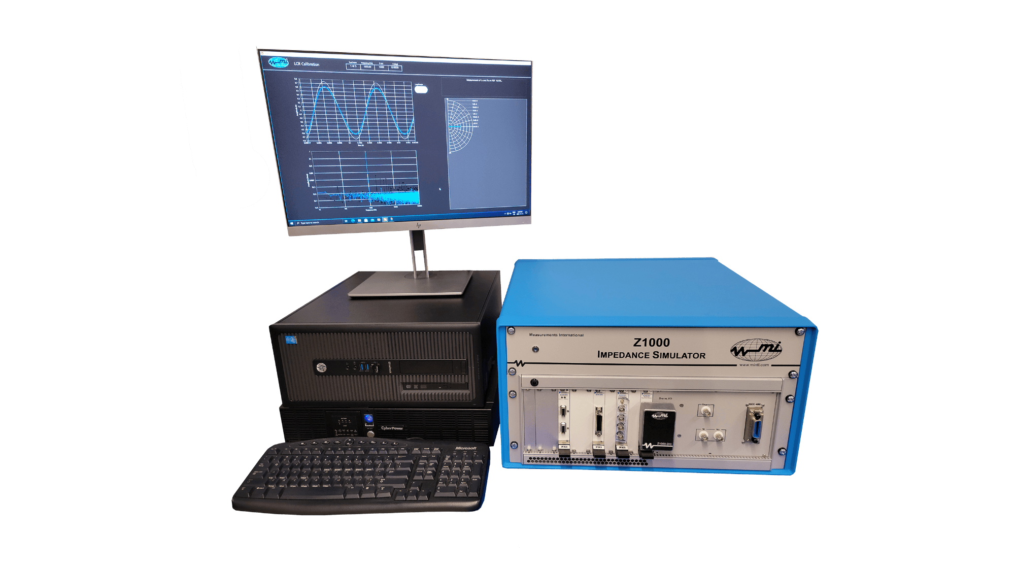
With the release of the commercial Z1000 iSimulator, the process for calibration of LCR meters has been taken to a new level. The Z1000 covers the full calibration of LCR meters over simulated impedances from 100 Hz to 20 kHz while eliminating the need for external standards and providing a much simpler, easier-to-use method of LCR meter calibration.
| Feature | Benefit |
| One instrument full LCR meter calibration. | Simple, easy-to-use method of calibration of LCR meters. |
| Only two probes (resistors) require calibration. | Cost savings of not having to have artifacts calibrated. |
| Characterization over full range. | Not limited in the range like artifact method. |
| Eliminates external standard requirements. | Eliminates manual artifact method, requires little space. |
| Large frequency range 100 Hz to 20 kHz. | Calibrate a large range of LCR meters. |
| NMI METAS design. | Design and instrumentation industry proven by leading experts. |
| Fully automated software. | All calculations and work are already done in the provided software. |
The Measurements International model Z1000 prototype and initial design were done by METAS in Switzerland. It was designed to address and fill the need and requirement for a better way to calibrate LCR meters. The current method of calibration of LCR meters requires highly accurate impedance standards (inductors, capacitors and resistors) that have to have traceability maintained, in which the procedure for calibration is time-consuming and requires a lot of manipulation of the standards making the measurement procedure complicated. Another large drawback of the previous method was that only a small fraction of the measurement capability of the LCR meter is tested because the reference standards usually have a decade value and phase angles close to the -90 degrees (capacitors), 0 degrees (resistor) or 90 degrees (inductors).
If you are familiar with the current method used to calibrate LCR meters (external inductors, resistors, capacitors) then you are aware of the very time-consuming and multiple manual manipulation components of the process. The Z1000 was designed with this in mind. It was designed with a very user-friendly operational software that limits the customer’s need for manual changing of connections and offers a simple step-by-step operation that provides constant automatic verification of the setup, and automatic switching and measurement procedures.
Z1000 iSimulator Method
The Z1000 offers a new more advanced approach. In the Z1000, the current and the voltage measured by the LCR meter to calculate the impedance are independently generated by two external voltage sources.
Adjusting the amplitudes and the relative phase of the voltage sources, the synthesized impedance can cover the entire complex plane. This concept was first proposed in 1994. More recently, a new design of the Z1000 – based on recently available, high-grade electronics components – have been designed.
The Z1000 covers calibrations in the frequency range from 100 Hz to 20 kHz and the magnitude of the synthesized impedance ranges from 1 Ω to 10 MΩ with an arbitrary phase angle.
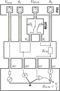
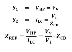
S1 supplies the voltage to HP, the second source S2 supplies the current to the LC port. Then the LCR meter calculates the value of the impedance. Because the two sources are independent, it is possible to arbitrarily choose the relative phase between the two, therefore the resulting impedance can be simulated to cover the entire complex plane.
A single MUX is used to accurately measure the actual voltage Vv supplied to HP input, and the voltage drop Vi generated by the current flow through ZCB.
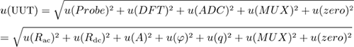
The uncertainty of the LCR meter calibration made with the use of the Z1000 is mostly depending on the accuracy of the LCR meter under test. This is because the uncertainty of the resistor is around 10-8 and the uncertainty of the clock is 10-12. Most LCR meters have a specification of about 500 ppm. When calculating the overall uncertainty, the resistor and clock are negligible!
Uncertainty Calculation
| Simulated Impedance | |
| Magnitude Range | 1 Ω to 10 MΩ |
| Phase Range | 90 deg to -90 deg |
| Resolution | 0.06 μΩ/Ω |
| Frequency | |
| Range | 100 Hz to 20 kHz |
| Resolution | 1 μHz |
| Accuracy | < 5 × 10-11 |
| Phase Noise | -55 dBc/Hz |
| Harmonic Distortion | -35 dBc |
| Probe | |
| DC Long-term Stability | < 2 × 10⁻⁶/year |
| Environment | |
| Operating Temperature, Humidity | 18 °C to 35 °C, 10 % to 80 % RH (non-condensing) |
| Storage Temperature, Humidity | -20 °C to 50 °C, 0 % to 90 % RH (non-condensing) |
| Line Voltage | 100 V to 240 V, 50 Hz/60 Hz |
| Atomic Clock (Optional) | |
| Frequency | 10 MHz |
| Phase Noise | -130 dBc/Hz |
| Harmonic Distortion | -25 dBc |
| Retrace | ± 5 × 10-11 |
| Mechanical | |
| Height | 330 mm (13 in.) |
| Width | 520 mm (20.5 in.) |
| Depth | 495 mm (19.5 in.) |
| Weight | 16 kg (35 lbs) |
| Warranty | 1 Year Parts & Labour |
1-800-324-4988
613-925-5934
Measurements International Ltd.
PB 2359, 118 Commerce Drive,
Prescott, Ontario, Canada K0E 1T0
© All Rights Reserved Measurements International