New Products
New products now available from Measurements International.
New products now available from Measurements International.
Introducing the all-new Model 6000C

A fully automated bridge designed to revolutionize the measurement of high-value resistors. Powered by advanced Cutkosky Divider technology, this innovative solution enhances accuracy while operating at lower currents. The Cutkosky (or Binary Voltage Divider) Technology eliminates the typical errors found in direct current comparators, offering unparalleled improvements in measurement uncertainty.
Equipped with a built-in guard circuit, the 6000C ensures optimal protection for the measuring circuit, and can also drive the measuring leads, as well as the guarded detector and resistor enclosures. This feature significantly boosts the effective insulation resistance, enhancing both the precision and overall performance of your measurements.
The Model 6000C is the ideal tool for high-precision resistor measurement, combining cutting-edge technology with unmatched reliability for your most demanding applications.
Featuring:
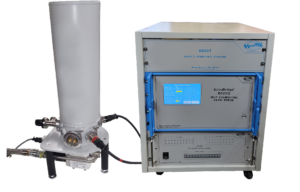
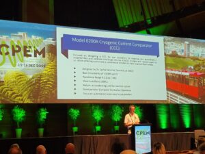
6200A Cryogenic Current Comparator (CCC)
Featuring:
Introducing the Model 6200A Cryogenic Current Comparator Bridge (CCC) from Measurements International (MI) – the ultimate solution for achieving the highest level of resistance calibration accuracy. With an uncertainty of less than 3 parts in 10-9, our CCC surpasses all other technology on the market.
Since 1987, MI has been a leader in providing the most accurate DCC room temperature resistance bridges, allowing customers to achieve unbeatable accuracy levels. However, with the introduction of the Model 6200A CCC, we are proud to take your resistance calibration capabilities to new heights.
Designed by Dr. Carlos Sanchez, a renowned expert in precision electrical metrology with years of experience in CCC Bridges and Quantum Hall Resistance Standards (QHR), the Model 6200A is the ultimate choice for metrology laboratories. Don’t settle for anything less than the best – trust MI to deliver unmatched accuracy and precision. Upgrade to the Model 6200A today.
6314A Precision Current Divider
Featuring
Overview
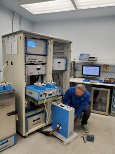
Measurements International has developed the 6314A Precision Current Divider with the aim to replace/ improve the outdated and often inaccurate Current Shunts being used. The 6314A is a 1000:1 Current Divider that works on the principal of the world-renowned MI Resistance Bridge and Extenders. Traditional Current Shunts suffer from temperature stability and power coefficient issues that greatly affect the users ability to make accurate measurements. The current transformer used in the 6314A has no such issues. The 6314A uses the ratio of two sets of windings on a DC Current Comparator (DCC) to divide the input current by 1000. The 6314A minimum current is 150 A, and the maximum current is 3000 A.
The 6314A can accept both DC and AC current with the uncertainty of approximately 20 times less than a DC Current Shunt.
The 6314A can also be combined with the 6311A to reduce very large currents down to mA. For instance, a 6314A can be used to divide up to 3000 A down to 3 A, which can be further divided to 30 mA using a 6311A. In this way a 1 Ω standard resistor and an 8 ½ digit DMM can be used to measure 3000 A with uncertainties of a few ppm.
Since 1993, MI has earned a worldwide reputation for Dependability, Quality, and Performance.
| Feature | Benefit |
| No Temperature Coefficient | Reduces uncertainty |
| No Stabilization Period | Measurements can be made immediately |
| No Power Coefficient | No error difference from 5% to 100% of the range |
| AC/DC | DC or AC Operation |
| CT/Current Divider | Current In is divided by 1000 |
| < 5 ppm (DC) / < 20 ppm (AC) | ∼ 20 times less than a traditional Current Shunt |
| Low Cost of Ownership | Without the need for routine calibration, it saves on calibration and shipping costs |
Featuring
Overview
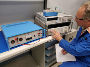
Measurements International has developed the 6311A Precision Current Divider with the aim to replace/improve the outdated and often inaccurate Current Shunts being used. The 6311A is a 100:1 and 1000:1 Current Divider that works on the principal of the world renowned MI Resistance Bridge and Extenders. Traditional Current Shunts suffer from temperature stabilities and the power coefficient issues that greatly affect the users ability to make accurate measurements. The current transformer used in the 6311A has no such issues. Simply apply power and measure the divided output. The 100:1 range has a maximum current of 10A and the 1000:1 range has a maximum current of 300A. Both ranges can accept both DC and AC current to 1kHz with uncertainty of < 5 and < 20 parts in 106 respectively. In comparison, a DC Current Shunt will have a calibration uncertainty of 0.01% or larger in most cases.
Since 1993, MI has earned a worldwide reputation for Dependability, Quality, and Performance. The 6311A uses the ratio of two sets of winding on a DC Current Comparator (DCC) to measure.
| Feature | Benefit |
| No temperature coefficient | Reduces uncertainty |
| No stabilization period | Measurements can be made immediately |
| No power coefficient | No error difference from 5% to 100% range |
| AC/DC | Works at DC and AC up to 1kHz |
| CT/Current Divider | Current In is divided by either 100 or 1000 |
| < 5 ppm DC / 20 ppm AC | Approximately 1/20th of a traditional Current Shunt |
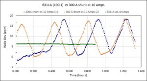
6311A Graph 2
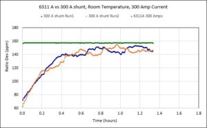
6311A Graph 1
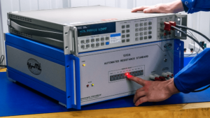
Developed & designed by metrologists for metrologists & calibration technicians
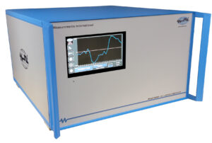
Measurements International’s new Automated Resistance Standard model 1310A is an easy-to-use, cost-effective calibration instrument that will give the military sector, national and third-party laboratories complete confidence in resistance standards. Designed with input from a world-leading National Measurement Institute, customers can be confident this new design offers exceptional calibration results.
| Feature | Benefit |
| 9 resistors 1 Ω, 10 Ω, 100 Ω, 1 kΩ, 10 kΩ, 100 kΩ, 1 MΩ, 10 MΩ, 100 MΩ, 1 external channel. | Complete line of decade value standards in one temperature-controlled enclosure. |
| Hand-picked high-precision resistors in a temperature-controlled chamber. | Delivers the highest level of performance from the internal high precision resistors. |
| Internal resistance elements in a temperature-controlled chamber. | Excellent stability and extremely low-temperature coefficients. |
| Single output cable for direct plug-in. | Easy operation without the requirement for changing wires. |
| Built for calibration of calibrators and DVMs. | Best stability < 2.5 μΩ/Ω/Year. |
| Built-in 4-terminal scanner. | Combining two instruments into one simple-to-use instrument. |
| External extra channel. | Connect to resistance value of your choice. |
| Front panel or GPIB controlled. | Simplifies operation for user. |
| Internally mounted temperature sensor PT100. | Users can connect to front panel and monitor internal oven. |
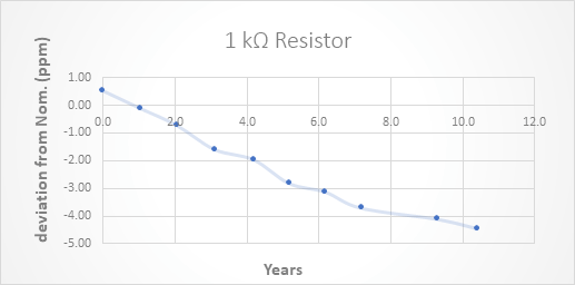
Figure 1. Drift of MI Resistor Over a 10 Year Period
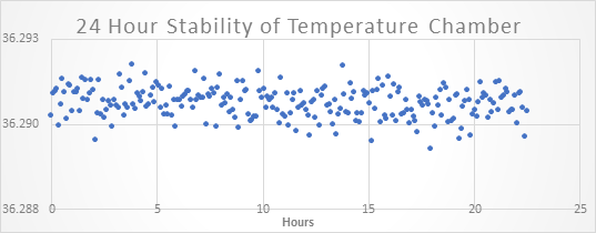
Figure 2. 24 Hour Stability Testing Internal Temperature Chamber
Three Standards – One Box
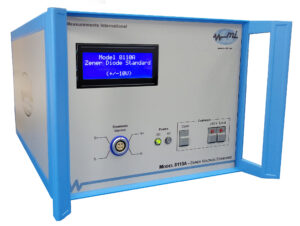
Measurements International’s recently launched Artifact Transfer Standard (1330A) is a highly versatile, accurate instrument that meets laboratory requirements for automated artifact calibration (to assign values to internally generated parameters) on calibrators and DMMs.
This process is typically performed using a small number of standards at recommended calibration intervals indicated in the calibrator or DMM manufacturers manual. The 1330A is composed of a temperature-controlled instrument enclosure, three reference standards, and a battery backup. A power supply is external (part of the power cable).
| Feature | Benefit |
| Primary 1 Ω, 10 kΩ and 10 V references. | All standards provided in one temperature-controlled enclosure. |
| Clear connection for JVolt Comparison of 10 V Zener. | Providing highest level traceability. |
| Manual (push buttons on the front panel) or automated control (select by GPIB interface). | Ability to select appropriate standard (choice of 3) for calibration. |
| Output connections to calibrator or DMM on front panel. | Choice of cables available (and supplied) feature direct plug-in for 57XX series calibrators or to the 3458A DMM. |
| Current standard value is extrapolated from prior calibrations. | Enhanced automation and improved accuracy. |
| Oven temperature monitored by internal PRT. | Provides better performance of artifacts as the temperature environment is stable and controlled to less than 100 m°C. |
| Calibrated values of the standards entered in the unit. | No requirement for set-up. |
| Front panel display showing certification value. | Quick access and reference to information. |
Simplify Your Procedures. Simplify Your Work.
Never before has DC voltage calibration and/or verification of DVMs and calibrators been so easy or reliable. Measurements International’s recently launched 1340A is the metrology industry’s leading choice thanks to its simplistic design, backed with the best features for optimal performance.
Model 1340A is another fine example of MI’s history and world-leading experience in resistance. We invite metrologists and calibration technicians in national, military and third-party calibration laboratories to compare the performance of the 1340A against any products on the market today.
| Feature | Benefit |
| 10:1, 100:1 and 1000:1 reference divider outputs to 1100 V | Extreme precision to compare direct voltage levels of various sources to a 10 V voltage reference standard like a 1330A, 732B or 732C. |
| Industry-leading specifications require no self-alignment or calibration prior to use. | Customers no longer need to self-align or calibrate prior to each use. Saves time and money and frustration! |
| Utilizes a special design network of high precision resistors mounted in a temperature-controlled chamber. | Shields divider resistors from outside noise and provides temperature stability to improve performance. |
| Front panel direct connection to calibrator; divider output connection to DVM for testing; both done with supplied cables. | Ease of use, saves time and money. |
| Internally mounted temperature sensor PT100. | Users can connect to the front panel and monitor internal oven. |
| New special hand-selected resistors and configuration. | Lengthy, self-alignment is no longer required to create a divider network. |
| Calibration of divider performed directly against a 1330A, 732B or 732C reference. | Industry-leading advancement in the DC voltage divider commercial products which delivers exceptional performance. |
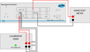
1340A Diagram
Figure 1. Example: 1000 V in divided to 10 V out to be measured
Offering the easiest-to-use instrument with complete confidence.
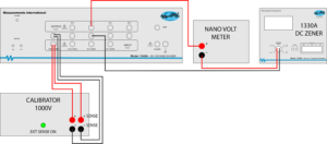
1340A Diagram 2
Figure 2. The above diagram illustrates using a 1330A, 732B or 732C reference in the connection sequence. A DVM can be used as a NULL detector to determine the offset of the 57XX series on the 10:1 and 100:1 ratio.
No Self-Alignment Required
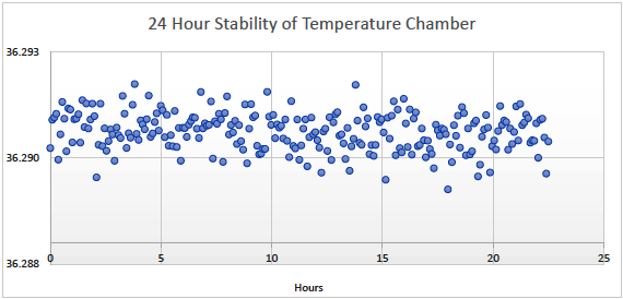
Figure 3: 24-Hour Stability of Temperature Chamber
1-800-324-4988
613-925-5934
Measurements International Ltd.
PB 2359, 118 Commerce Drive,
Prescott, Ontario, Canada K0E 1T0
© All Rights Reserved Measurements International