Accurately measuring electric energy in high-voltage, high-current distribution systems relies on three key components:
If the instrument transformers are not calibrated with similar accuracy, then the measuring device’s measurements will be with high uncertainties. For high voltages and currents, this inaccuracy can have a significant impact on the result. Ensure precision from the start—MI’s 17025-accredited lab can calibrate these instruments with NMI traceability. This means accuracy from the first measurement you take.
Beginning with single instruments, such as an automated, high-voltage capacitance tan delta bridge, high-voltage dividers, wattmeters/power analyzers, and systems, like the MI Power Calibration System (PCS), Automated Load Loss Measurement System (ALMS), and Isolating Current Transformer (ICT) system.
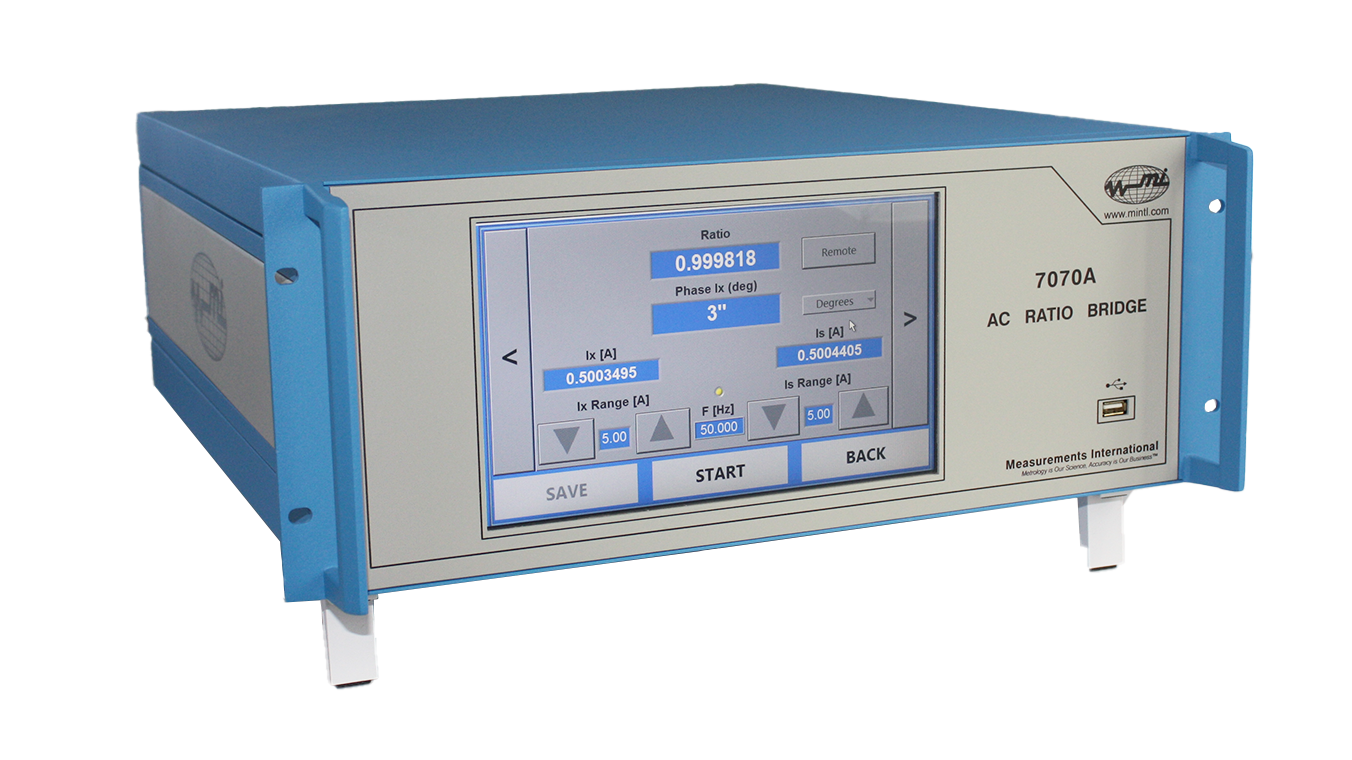
MI’s 7070A series of fully-automated AC ratio bridges were developed for fast and accurate measurements of instrument transformer errors. Integrate the 7070A into complex systems to calibrate voltage transformers up to 800 kV and current transformers to 10,000 A. The 7070A sets new measurement standards in instrument transformers calibration.
Model 7070A-U
The 7070A-U is an AC Voltage Ratio Bridge for calibrating voltage transformers using either a standard reference voltage transformer, a high-voltage standard capacitor, or a standard reference voltage divider. The instrument has six input voltage ranges: 6, 15, 30, 60, 150, and 300 V. Combine the 7070A-U with a 2500-series high-voltage divider for single-setup testing, where the HV divider provides 100 V output on each range. The HV divider output voltage and UUT output voltage are applied directly to the AC Voltage Ratio Bridge’s input channels.
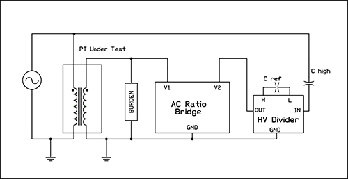
Figure 1. Model 7070A-U Voltage Transformer configuration
using a high-voltage capacitor and MI HV divider.
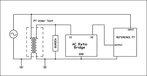
Figure 2. Model 7070A-U Voltage Transformer configuration
using a high-voltage reference potential transformer.
Measurement Systems
MI designs and supplies system solutions for current and voltage transformer measurements customized for specific requirements. Some of the system components are listed below:
1. 7020 series standard current transformers
2. 7200 series of current comparators
3. 2500 series of voltage dividers
4. Model CG series of high-voltage capacitors
5. Electronic burdens
6. Computer and printer for external control and data recovery.
| Model No. | 7070A-U | ||
| Input Channels | 2 | ||
| Current Measurements | |||
| Input Ranges per Channel (A) | N/A | ||
| Current Accuracy (ppm of FS) @ 50/60 Hz (23 °C ± 5 °C) |
N/A | ||
| Ratio Accuracy (ppm) (23 °C ± 5 °C) |
|
||
| Phase Shift Accuracy (min) (23 °C ± 5 °C) |
|
||
| Linearity (ppm) | N/A | ||
| Input Impedance (Ω) | N/A | ||
| Isolation (Vpp) | N/A | ||
| Frequency Range (Hz) | N/A | ||
| Voltage Measurements | |||
| Input Ranges per Channel (V) | 6, 15, 30, 60, 150, 300 | ||
| Voltage Accuracy (ppm of FS) @ 50/60 Hz (23 °C ± 5 °C) |
± 50 | ||
| Ratio Accuracy (ppm) (23 °C ± 5 °C) |
|
||
| Reading Resolution | 1 ppm | ||
| Phase Shift Accuracy (min) (23 °C ± 5 °C) |
|
||
| Linearity (ppm) | ≤ 20 | ||
| Input Impedance (MΩ) | 5 | ||
| Frequency Range (Hz) | 15 to 100 Hz | ||
| Power Measurements | |||
| Line-to-Neutral (ppm of FS) @ 50 or 60 Hz (23 °C ± 5 °C) |
|
||
| Line-to-Line (ppm of FS) @ 50 or 60 Hz (23 °C ± 5 °C) |
|
||
| Operating Environmental Conditions | |||
| Temperature (°C) | 15 to 40 °C | ||
| Relative Humidity | 10 to 80 % (RH) Non-condensing |
||

1-800-324-4988
613-925-5934


Measurements International Ltd.
PB 2359, 118 Commerce Drive,
Prescott, Ontario, Canada K0E 1T0


© All Rights Reserved Measurements International