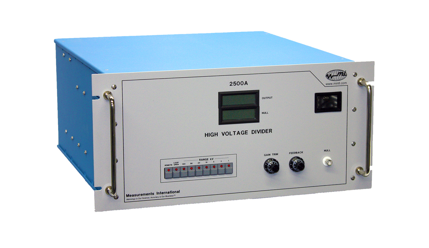
The model 2500A, 2501A, 2502A and 2503A complete the low-voltage arm of a high-voltage capacitive divider. Based on the compensated-current-comparator, it provides ultra-precise ratio division of high AC voltages down to measurable levels. The output of the divider can be read by a long-scale DMM or AC/DC transfer device to precisely determine the input voltage. It can also be read by a precision power analyzer such as the MI model 2020A for direct measurements of the transformer or reactor losses under control of the IEEE-488 interface. Each divider comes equipped with 7 voltage ranges of 1, 2, 5, 10, 20, 50 and 100.
| Feature | Benefit |
| Current comparator-based design. | Very high voltage division accuracy. Outstanding linearity over the full operation range. |
| Front panel or IEEE control. | Automated or stand-alone operation. |
| Feedback loop circuit with Reference Capacitor. | Keeps control of the accuracy over a long period of time and/or temperature change. |
| Seven voltage division range. | Eliminates the need to use multiple standard PTs. |
| Front panel indicators. | For visual monitoring of measurement and operation. |
| Auxiliary scaled and not scaled outputs. | Auxiliary outputs can be used for automation and control without affecting or loading main output signal. |
Model 2500A: The input current to the model 2500A is given by applying a high-voltage to a low-loss high-voltage capacitor (100 pF/120 kV for 120 kV, 50 pF/250 kV for 240 kV) on its input. Several gain stages of 1, 2, 5, 10, 20, 50 and 100 are built in to allow flexibility for various input voltages. On gain 1, the full-scale input is 120 kV; while gain 100 offers a full-scale input of 1.2 kV. The full-scale output is 120 V for 120 kV input with a 10 % overrange. For a 100 pF, 100 kV input capacitor the full-scale output is 100 V.
To apply 240 kV to the same divider, a 50 pF, 250 kV standard capacitor is used on the input. On gain 1, the full-scale input is 240 kV, while gain 100 offers a full-scale input of 2.4 kV. The full-scale output is 120 V for 240 kV in with a 10 % overrange. For a 50 pF, 200 kV input capacitor the full-scale output is 100 V.
Model 2501A: The model 2501A will accept inputs up to 2.4 kV using a 1,000 pF, 2.4 kV or higher standard capacitor on its input. On gain 1 the full-scale input is 2.4 kV; while gain 100 offers a full-scale input of 120 V. The full-scale output for each range is 120 V.
Model 2502A: The model 2502A will accept inputs up to 480 kV when a 100 pF standard capacitor is used, and 960 kV when a 50 pF standard capacitor is used on the input. Several gain stages of 1, 2, 5, 10, 20, 50 and 100 are built in to allow flexibility for various input voltages. On gain 1, the full-scale input is 480 kV while gain 100 offers a full-scale input of 4.8 kV. The full-scale output is 120 V for all ranges. For an input capacitor of 50 pF, the full-scale input is 960 kV. On gain 1 the full-scale input is 960 kV while gain 100 offers a full-scale input of 9.6 kV.
Model 2503A: The model 2503A will accept inputs up to 360 kV when a 50 pF, 400 kV standard capacitor is used on its input. Several gain stages of 1, 2, 5, 10, 20, 50 and 100 are built in to allow flexibility for various input voltages. On gain 1 the full-scale input is 360 kV, while gain 100 offers a full-scale input of 3.6 kV with 10 % overrange. The full-scale output is 120 V for all ranges. For an input capacitor of 100 pF, 300 kV the full-scale input is 300 kV. On gain 1 the full-scale input is 300 kV while gain 100 offers a full-scale input of 3.0 kV with a full-scale output of 100 V.
A 1,000 pF low-loss stand capacitor is supplied with each unit as the reference capacitor. An optional high-voltage capacitor ranging from 2 kV to 800 kV can be ordered to be used on the input of the divider.
Operating Principle: A simplified schematic of the current comparator based voltage divider is shown in Figure 1. The current in the low-loss high-voltage capacitor (CH) is compared, using the current comparator, with the current obtained by applying the output voltage VL to a stable low-loss standard capacitor (CL).
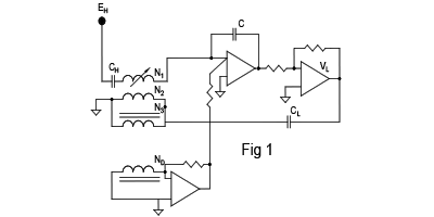
The main advantage of the 2500A is that the ND winding in the current comparator automatically corrects for any magnitude or dissipation errors in the divider by adding the current in the detection winding through the feedback circuit to the current in the solid dielectric capacitor Cf resulting in a highly accurate and self-balancing voltage at VL. There are no adjustments required, accuracy can be maintained for years.
Applications
1. Reactor Loss Measurement Systems
2. Transformer Loss Measurement Systems
3. AC High-Voltage Measurement Systems
4. Power Calibration Systems
5. Calibration of Standard Voltage Transformers
6. Calibration of Standard AC Resistive Dividers
The 250XA High-Voltage Divider series gives users unprecedented flexibility when it comes to accurate scale-down of AC high-voltage. One instrument can used in combination with input capacitors of different nominal values expanding the division capability even more than just the seven built-in ranges. For example, the 2500A model when used with a 100 pF input capacitor can be used up to 100 kV. However, the same instrument with a 50 pF input capacitor can double the range and be used up to 200 kV. The table below shows other models’ capability with different HV input capacitor.
The high-voltage divider can be used as a stand-alone unit or in combination with other instruments for a large variety of applications. It can be used with wattmeters for accurate power measurements like Loss Measurement Systems, Power Calibration Systems and more.
It can also be used with AC Ratio Bridges and AC Capacitance bridges for calibrating Precision Voltage Transformers or any other AC voltage divider.
The current comparator technology design allows the instrument to be used also with AC Standard Resistors connected to its input or as a current to voltage precision converter. For more details about this or any other application, please contact your MI representative.
2500A
| Input Capacitor 100 pF | Input Voltage: 120, 60, 24, 12, 6, 2.4, 1.2 kV |
| Output Voltage: 120 Volts | |
| Input Capacitor 50 pF | Input Voltage: 240, 120, 48, 24, 12, 4.8, 2.4 kV |
| Output Voltage: 120 Volts |
2501A
| Input Capacitor 1000 pF | Input Voltage: 2400, 1200, 600, 480, 360, 240, 120 V |
| Output Voltage: 120 Volts |
2502A
| Input Capacitor 100 pF | Input Voltage: 480, 240, 96, 48, 19.2, 9.6, 4.8 kV |
| Output Voltage: 120 Volts | |
| Input Capacitor 50 pF | Input Voltage: 960, 480, 192, 96, 38.4, 19.2, 9.6 kV |
| Output Voltage: 120 Volts |
2503A
| Input Capacitor 50 pF | Input Voltage: 300, 150, 60, 30, 15, 6, 3 kV |
| Output Voltage: 100 Volts |
General
| Maximum Output Voltage | 120 VAC RMS with 10 % Overrange |
| Division Ratio Uncertainty | Magnitude < 20 ppm Quadrature < 20 ppm |
| Frequency Range of Measured Values | 40 Hz to 400 Hz |
| Gain Selection | 7 Gain Setting of 1, 2, 5, 10, 20, 50, 100 |
| Warm-Up Time | < 5 Minutes to Full Rated Accuracy |
| Operating Environment | 10 to 34 °C, 10 to 18 % RH |
| Warranty | 1 Year Parts & Labour |
1-800-324-4988
613-925-5934
Measurements International Ltd.
PB 2359, 118 Commerce Drive,
Prescott, Ontario, Canada K0E 1T0
© All Rights Reserved Measurements International