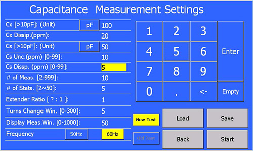
The 7010C is a microprocessor-controlled, current comparator based, automated capacitance bridge with metrology capabilities. However, it can also be used to measure inductance, reactor loss, AC resistance and the calibration of MI CTs. When used to measure capacitance the ratio of two capacitors (Cx/Cs) or the value of the capacitor Cx in capacitance units (pF to µF) or both are displayed along with the dissipation reading of the measurement. The minimal voltage that can be applied is 100 V when measuring a 1000 pF capacitor. To display the value of Cx, the value of the reference capacitor Cs must be known and entered through the touch screen before measurements start.
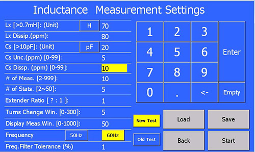
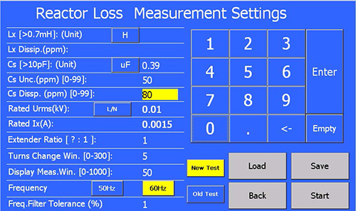
When it is used to measure inductance it displays either the ratio of 2 reactances (Xl/Xc, where Xl is the reactance of Lx, and Xc is the reactance of Cs) or the value of an unknown inductor in (mH to H). When measuring reactor loss, it displays inductance and various calculated parameters, such as power, power factor, input voltage and frequency. To display the value of L the value of the reference capacitor Cs must be known and entered through the touch screen before measurements start.
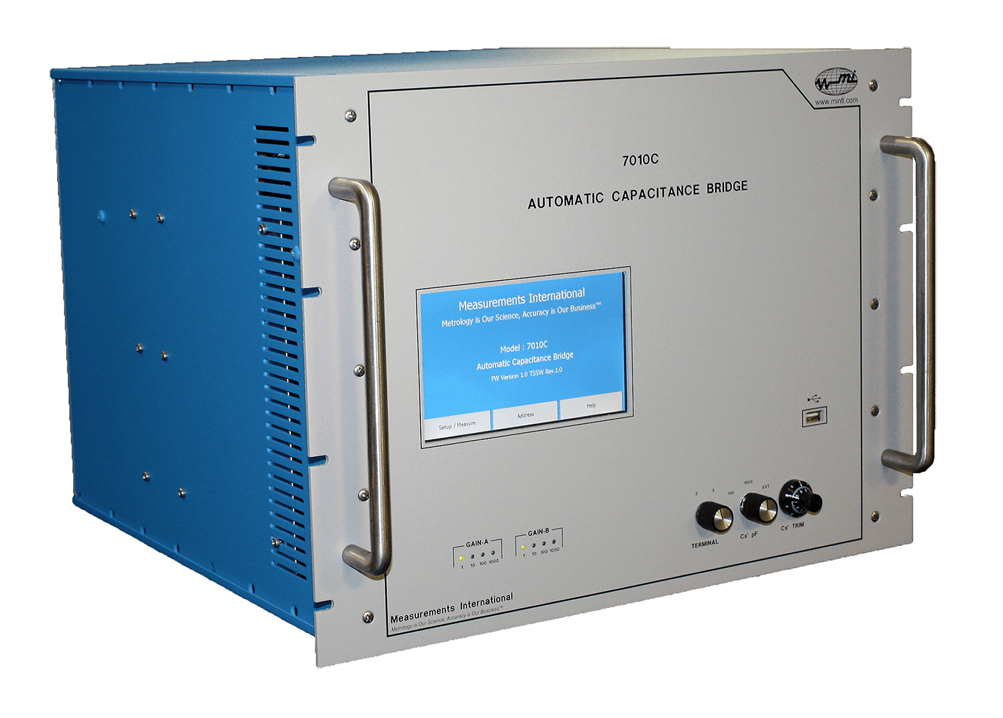
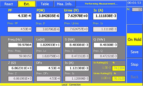
A large touch screen display presents relevant measuring quantities such as capacitance (Cx) and dissipation factor (Tan δ). Easy to use touch screen menus allows the operator to set up the measurements including the number of readings for statistical analysis of uncertainty calculations at the 95 % (2 s) level. The touch screen display can display a table of values. All measured parameters related to capacitance and inductance measurements can be transmitted over the IEEE-488 interface for storage to a computer. The 7010C measures and displays the current through the standard capacitor (Cs) and the applied input voltage and frequency of measurement. A USB slot is provided on the front panel for saving measurement data and parameters.
The principle of the 7010C is based on the two-stage-compensated current comparator. The automatic self-balancing feature facilitates the use of the bridge for accurate load loss measurements of large high-voltage inductive loads. This is a major advantage over the manual capacitance bridges which have difficulty in following frequency changes.
The model 7010C has the following ratios: 1:1, 2:1, 5:1, 10:1, 20:1, 50:1, 100:1, 200:1, 500:1 and 1000:1 with an overall accuracy of < 15 ppm in magnitude and 1 % of reading ± 10 ppm in dissipation. The dissipation (loss tangent) has a range of 0 to 10 % with a resolution of 1 ppm making it ideal for both low and high-voltage applications.
To accommodate capacitance ratios larger than 1000:1 an additional two-stage range extender, model 7020, may be added to increase the ratio to 2,000,000:1. All connections are made on the rear of the instrument. The effect of lead length on the measurement accuracy has been reduced by means of a built-in lead compensation circuit. An optional shielded rack on castors is available for portability on the test floor.
Applications for the 7010C include:
| Shunt Reactor Loss Measurements | Power Transformer Measurements |
| Calibration of Potential Transformers | Calibration of Low-Voltage Std. Capacitors |
| Calibration of High-Voltage Dividers | Calibration of High-Voltage Power Capacitors |
| Inductance Measurements | Measurement of Low Loss, High-Voltage Power |
| Loss Tangent Measurements to 10 % | Corona Loss Measurements |
| Insulator and Dielectric Testing | |
Capacitance Measurement and Calibration
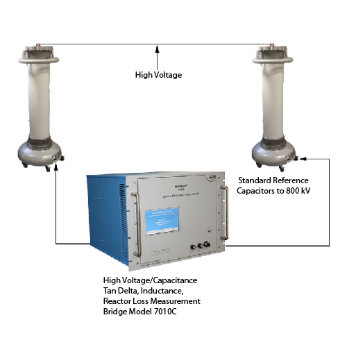
The 7010C is capable of performing both 2 and 3 terminal capacitance measurements. Three terminal measurements (lead compensation) are typically performed when very large capacitors are to be measured to remove the lead impedance. For capacitance measurements, the 7010C has a maximum ratio of 1000:1 for measurement of capacitance and a Cs range of 10 pF to 10,000 pF. To extend the ratio of the 7010C an additional range extender model 7020 with a ratio of up to 2000:1 can be added extending the ratio to 2,000,000:1. A large touch screen display on the 7010C is used to set up and display the measurements. Several high-voltage capacitors are also available ranging from 50 kV up to 800 kV with values of 50 pF and 100 pF.
Voltage Transformer Calibration
Voltage transformers can be calibrated using the 7010C and two high-voltage standard capacitors. The ratio of the capacitors is first measured at the voltage that the transformer is measured at. The high-voltage supply is then used to feed both the voltage transformer and the two high-voltage standard capacitors. During the calibration of the voltage transformer, the two high-voltage capacitors are interchanged and the voltage ratio can be calculated and the dissipation reading on the 7010C is the loss of the voltage transformer. The below table shows a possible combination of ratios and capacitors but not limited to these values.
| Transformer Ratio |
Cs1 | Cs2 | Max Cs2 Volts | Bridge Ratio 1 |
Bridge Ratio 2 |
| 1 | 1000 pF | 1000 pF | 26 kV | 1 | 1 |
| 100 | 1000 pF | 1000 pF | 26 kV | 1 | 100 |
| 10 | 1000 pF | 100 pF | 260 kV | 10 | 1 |
| 1000 | 1000 pF | 100 pF | 260 kV | 10 | 100 |
| 100 | 5000 pF | 50 pF | 520 kV | 100 | 1 |
| 10000 | 5000 pF | 50 pF | 520 kV | 100 | 100 |
Note: The same specifications for accuracy of the 7010C Capacitance Bridge apply to each of the two measurements required for voltage transformers. Any voltage coefficient of the Cs1 and Cs2 capacitor should be taken into account when calculating the voltage ratio.
Inductance Measurement
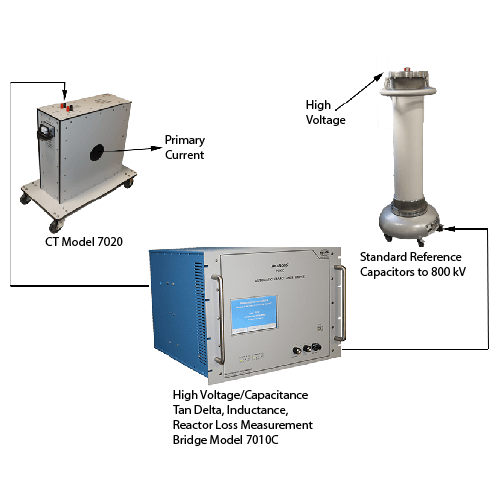
The Capacitance Bridge is capable of measuring inductors by automatically reversing the primary winding. This reactive component of current when reversed is in phase with the current through the standard capacitor and a bridge balance can be obtained with the display reading in terms of equivalent inductance ratio.
Note: The accuracy of the bridge in the measurement of the capacitance ratio does not depend essentially on the accuracy of the frequency. However, in measuring inductance, the frequency of the supply can be the dominating factor.
The 7010C handles frequency changes by measuring the frequency and updating the display. Several transformer manufacturers use the MI 7010C, 7020 and an MI high-voltage capacitor combination for measuring inductance and reactor losses. Systems as high as 600 kV have been built. The range of the 7010C can be extended for the measurement of inductance using the 7020 Two-Stage Compensated Current Transformer which has a single ratio up to 2000:1. The combined ratio of the 7010C and 7020 is 2,000,000:1. See the inductance measurement range table for a complete range of inductance measurements.
| Capacitor Cs (pF) |
Max Voltage @ 50 Hz (V) |
Bridge Ratio |
Extender Ratio |
Max Inductance (H) |
Max Inductor Current (A) |
| 10000 | 3180 | 723 | 2 | 0.7 | 14.46 |
| 10000 | 3180 | 723 | 20 | 0.07 | 144.6 |
| 10000 | 3180 | 723 | 200 | 0.007 | 1446 |
| 10000 | 3180 | 723 | 2000 | 0.0007 | 14460 |
| 1000 | 31800 | 723 | 2 | 7 | 14.46 |
| 1000 | 31800 | 723 | 20 | 0.7 | 144.6 |
| 1000 | 31800 | 723 | 200 | 0.07 | 1446 |
| 1000 | 31800 | 723 | 2000 | 0.007 | 14460 |
| 100 | 318000 | 723 | 2 | 70 | 14.46 |
| 100 | 318000 | 723 | 20 | 7 | 144.6 |
| 100 | 318000 | 723 | 200 | 0.7 | 1446 |
| 100 | 318000 | 723 | 2000 | 0.07 | 14460 |
| 50 | 636000 | 723 | 2 | 140 | 14.46 |
| 50 | 636000 | 723 | 20 | 14 | 144.6 |
| 50 | 636000 | 723 | 200 | 1.4 | 1446 |
| 50 | 636000 | 723 | 2000 | 0.14 | 14460 |
| Capacitor Cs (pF) |
Max Voltage @ 60 Hz (V) |
Bridge Ratio |
Extender Ratio |
Max Inductance (H) |
Max Inductor Current (A) |
| 10000 | 2650 | 1005 | 1 | 0.7 | 10.04 |
| 10000 | 2650 | 1005 | 10 | 0.07 | 100.4 |
| 10000 | 2650 | 1005 | 100 | 0.007 | 1004 |
| 10000 | 2650 | 1005 | 1000 | 0.0007 | 10041 |
| 1000 | 26500 | 1005 | 1 | 7 | 10.04 |
| 1000 | 26500 | 1005 | 10 | 0.7 | 100.4 |
| 1000 | 26500 | 1005 | 100 | 0.07 | 1004 |
| 1000 | 26500 | 1005 | 1000 | 0.007 | 10041 |
| 1000 | 26500 | 1005 | 2000 | 0.0035 | 20083 |
| 100 | 265000 | 1005 | 1 | 70 | 10.04 |
| 100 | 265000 | 1005 | 10 | 7 | 100.4 |
| 100 | 265000 | 1005 | 100 | 0.7 | 1004 |
| 100 | 265000 | 1005 | 1000 | 0.07 | 10041 |
| 100 | 265000 | 1005 | 2000 | 0.035 | 20083 |
| 50 | 530000 | 1005 | 1 | 140 | 10.04 |
| 50 | 530000 | 1005 | 10 | 14 | 100.4 |
| 50 | 530000 | 1005 | 100 | 1.4 | 1004 |
Note: If other Inductance Measurement Ranges are required, contact Measurements International
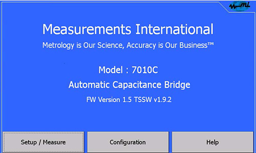
When 7010C power switch is turned on – the touch screen will automatically load the program and the bridge will perform initialization routines, calibrate its A/D converters, etc.
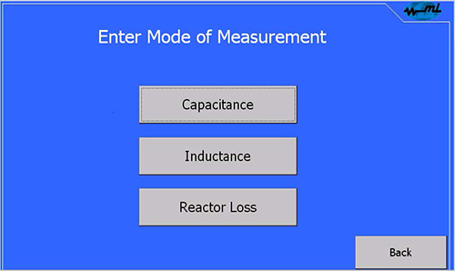
From the touch screen panel, it is possible to fully operate the bridge performing the capacitance, inductance and reactor loss measurements.
For each measurement, the user will be prompted to enter the parameter setting page.
| Capacitance Range | Cs: 10 pF to 10,000 pF Cx: 10 pF to 10,000,000 pF (10 µF) |
| Capacitive Ratio 1:1 to 1000:1 | Ns: 0 to 1.11110 in steps of 0.000001 Nx: 1 to 1000 in steps of 1, 2, 5 |
| Primary Current | 10 Amp Maximum |
| Secondary (Cs) Current Range | 40 µA to 10 mA |
| Dissipation Factor Range | 0 to 10 % in steps of 0.000001 |
| Inductance Range | 700 µH to 700000 H (Q factor > 10) |
| Test Frequencies | 50 and 60 Hz |
| Accuracy | Ratio: ± 15 ppm for all Cx Ratios |
| Loss Angle | ± 1 % of Reading ± 10 ppm |
| Display | 7-inch Screen Display |
| Warm-Up Time | < 5 Minutes to Full Rated Accuracy |
| Operating Environment | 18 to 34 °C, 10 to 80 % RH |
| Operating Power | 100, 120, 220, 240 V – 50/60 Hz |
1-800-324-4988
613-925-5934
Measurements International Ltd.
PB 2359, 118 Commerce Drive,
Prescott, Ontario, Canada K0E 1T0
© All Rights Reserved Measurements International