Self-Calibration Quantum Hall Ratio Resistance Bridge
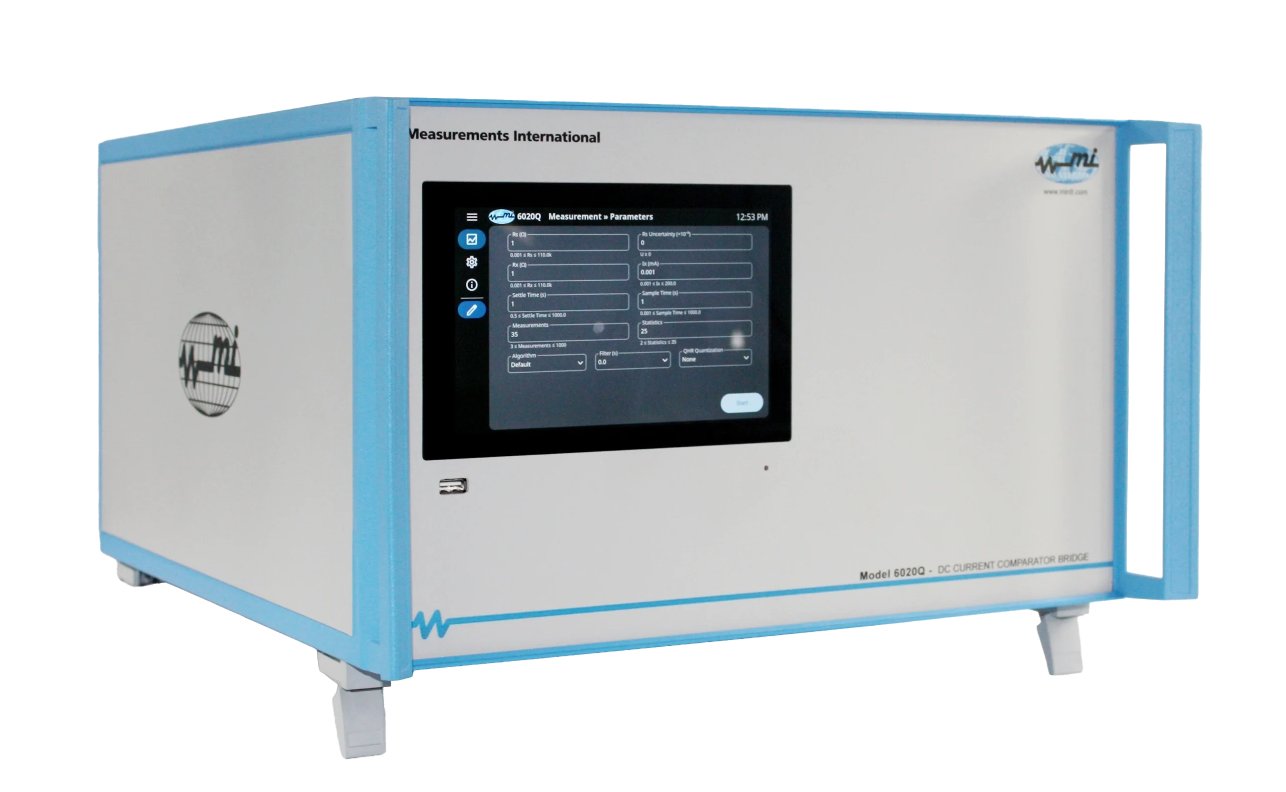
As the leading provider of top-notch resistance measuring equipment, Measurements International (MI) proudly presents the AccuBridge® 6020Q Automated Resistance Bridge. Known for its exceptional speed, precision, and measurement accuracy, the 6020Q is the preferred choice of National Measurement Institutes (NMIs) across the world. Its innovative design and user-friendly operation make it an ideal solution for stand-alone resistor calibrations and primary resistance measurements. With its unparalleled performance, the 6020Q is sure to raise the bar in the world of resistance metrology.
| Feature | Benefit |
| DCCT based. | Provides excellent stability and range linearity. |
| Vcr, Vxx and Vxy measurements. | Supports dissipation and contact resistance checks. |
| Accuracy < 0.015 µΩ | Allows sub-ppm high-stability measurements. |
| Maximum Ratio 14:1 | Wide ratio range to cover laboratory standards and RK/2 |
| National lab continuity. | The only commercially available QHR resistance bridge used in primary or national laboratories worldwide. |
| Full DCC resistance range. | 0.1 Ω to 13 kΩ. |
| Stable low currents. | 1 μA to 200 mA ensures ultra-low noise measurements. |
| Resistance Measurement 0.1 Ω to 13 kΩ |
|||
| Range
(1:1 Ratio) |
Uncertainty
(µΩ/Ω) |
Range
(1:10 Ratio) |
Uncertainty
(µΩ/Ω) |
| 0.1 Ω to 0.1 Ω | 0.15 | 0.1 Ω to 1 Ω | 0.1 |
| 1 Ω to 1 Ω | 0.015 | 1 Ω to 10 Ω | 0.015 |
| 10 Ω to 10 Ω | 0.015 | 10 Ω to 100 Ω | 0.015 |
| 100 Ω to 100 Ω | 0.015 | 100 Ω to 1 kΩ | 0.015 |
| 1 kΩ to 1 kΩ | 0.015 | 1 kΩ to 10 kΩ | 0.015 |
| 10 kΩ to 10 kΩ | 0.5 | 1 kΩ to 12.9 kΩ | 0.015 |
| Measurement Mode | 4-wire |
| Linearity | < 0.005 x 10⁻⁶ of full-scale |
| Operating Conditions | 10 °C to 35 °C, 10 % to 90 % RH non-condensing |
| Test Current Range | 1 μA to 200 mA |
| Test Current Resolution | 18-bit |
| Interface | IEEE-488 |
| Display | Touch-screen display (no external keyboard), resolution 0.001 x 10⁻⁶ |
1-800-324-4988
613-925-5934
Measurements International Ltd.
PB 2359, 118 Commerce Drive,
Prescott, Ontario, Canada K0E 1T0
© All Rights Reserved Measurements International