Measurements International’s AccuBridge® models 6010/150/300/3000 and 6242/150/300/3000 High Precision Direct Current Comparator (DCC) Shunt and High Precision Direct-Current Current Transformer (DCCT) measurement systems offer the greatest accuracy and lowest uncertainty of any commercially available system. Our high current range extenders expand the measuring capabilities of our 6010 and 6242 series bridges to measure lower resistance values at higher currents with accredited achievable uncertainties of < 20 ppm at 10 μΩ to 0.1 ppm at 1 Ω. Ratio uncertainties as low as 0.02 ppm are achievable at 1 Ω.
Measurements International is the original manufacturer of the Automated Resistance Measurement System. With the greatest current comparator experience in the industry, our shunt measurement systems are designed using sound metrology principles. As your accreditation partner and global support partner, MIL offers leading product knowledge and applications expertise through coaching, system design, implementation, calibration services and ongoing expert support, which assures your competitive advantage with all your MI products.
At MIL, it’s not only about the equipment or the science…
it’s about what that will enable you to do, and the ease with which you can do it.
Measurements International provides world-class expertise in DC resistance metrology to National Measurement Institutes (NMIs) and primary and calibration laboratories who need to achieve the lowest possible traceable uncertainty in their measurements and calibration equipment. As your accreditation and global support partner, MI helps ensure your competitive advantage by offering leading product knowledge and applications expertise through coaching, system design, implementation, calibration services, and ongoing expert support.
Measurements International’s series of shunt measurement systems are the only self-calibrating bridge systems that use a full 25-bit binary wound direct-current comparator (DCC). Our 6010 and 6242 series bridges are used worldwide to calibrate standard resistors and shunts as well as other manufacturer’s bridges and Shunt Measurement Systems.
Measurements International’s 6010 and 6242 series of Shunt Measurement Systems provide the widest range with the lowest uncertainty of any manufacturer. Our systems’ reversing switches have a negligible systematic error as compared to the current mismatch between positive and negative current supples. We are the only manufacturer to provide this.
The AccuBridge® 6010/150 or 6242/150 system includes the MI 6011 Range Extender and the 6150A (maximum 150 A) Power Supply to create an automatic Shunt Measurement System.
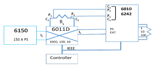
Figure 1: Shunt Calibration 6010/6011
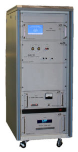
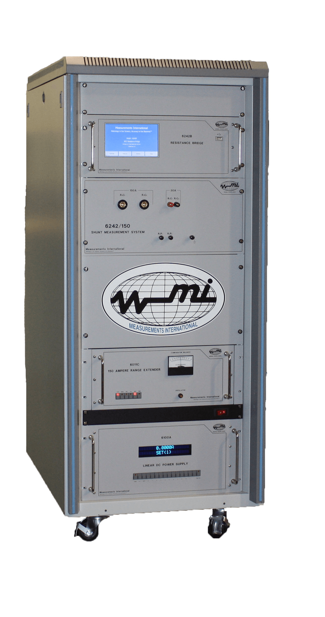
Figure 2: 6242/150 A System
Figure 1 shows the basic 6242/6011 Shunt Calibration System schematic and Figure 2 provides a front view of the system. You make high-current connections at the front of the rack.
You can expand the system using an MI 4220/30 A 20-Channel Matrix Scanner, allowing automated measurement of twenty 30 A shunts. For further expansion, the system is available in either a 1224 or 1530 mm height rack.
You can also use standard resistors of 1 Ω, 10 Ω, and 100 Ω to extend the ratio of MI’s 6011 range extenders for higher currents. For example, if a 0.01 Ω shunt needed to be calibrated at 100 A, you could calibrate it on range 1000 using a 10 Ω standard on Rs. Similarly, you could calibrate a 0.1 Ω shunt at 15 A on range 1000 using a 100 Ω standard.
Table 1 shows the system uncertainty based on the available ratio of 10, 100, and 1000 with currents of 1 A, 10 A and 150 A. Because this is a ratio device, you can improve the uncertainty through self-calibration techniques of the range extender. Lower uncertainties are available depending on the stability of your standards.
Table 1: 6010/6011/150 Ratio Uncertainty
| 6011/150 | 6010 | |||||||||||
| Rx | Test I | Range | Ratio | Output | Range | Vrx | Unc1 | Rs | Ratio | Irs | Vrs | Prs |
| Ω | A | A | S/M | A | % | V | ppm | Ω | M/S | A | V | W |
| 0.1 | 1 | 1 | 10 | 0.1 | 100 | 0.1 | 0.2 | 1 | 1 | 0.1 | 0.1 | 0.01 |
| 0.1 | 0.1 | 1 | 10 | 0.01 | 10 | 0.01 | 0.3 | 1 | 1 | 0.01 | 0.01 | 0.0001 |
| 0.01 | 10 | 10 | 100 | 0.1 | 100 | 0.1 | 0.2 | 1 | 1 | 0.1 | 0.1 | 0.01 |
| 0.01 | 1 | 10 | 100 | 0.01 | 10 | 0.01 | 0.3 | 1 | 1 | 0.01 | 0.01 | 0.0001 |
| 0.001 | 150 | 100 | 1000 | 0.15 | 100 | 0.15 | 0.2 | 1 | 1 | 0.1 | 0.1 | 0.01 |
| 0.001 | 10 | 100 | 1000 | 0.01 | 10 | 0.01 | 0.3 | 1 | 1 | 0.01 | 0.01 | 0.0001 |
| 0.0001 | 150 | 100 | 1000 | 0.15 | 100 | 0.015 | 0.3 | 0.1 | 1 | 0.1 | 0.01 | 0.001 |
| 0.0001 | 10 | 100 | 1000 | 0.01 | 10 | 0.001 | 0.4 | 0.1 | 1 | 0.01 | 0.001 | 0.00001 |
Note 1. Includes the uncertainty of the 6011 range extender and the 6010 or 6242 bridge and RSS with the standard deviation of the measurement (2 sigma)
Measuring Non-Decade Resistor Values
For optimum performance, the 6010 or 6242 bridges should be on ratio 1 when used with the 6011 range extender. You can also measure other ratios to cover the resistance range of 0.2 Ω to 0.9 Ω on the ratio 100 range using a 10 Ω as the reference resistor. The maximum output current of the 6011 is 200 mA. For lower current measurements, the standard deviation of the measurement may increase. When using reference resistors of 10 Ω and 100 Ω, you can apply higher currents to the shunt.
System Power
The systems can be powered from a 100 V, 120 V, 220 V, or 240 V single-phase power supply. To enhance mobility, the systems are mounted on wheels.
The 6010/300 A or 6242/300 A systems may be used in conjunction with MI’s 6011D/300 and the MI 6250A (maximum 300 A) Power Supply for measuring shunt resistances between 10 μΩ and 0.1 Ω. The 6011D/300 has ratios of 30, 300, and 3000 with input current ranges of 3 A, 30 A, and 300 A, respectively. The maximum full-scale output current is 100 mA on all ranges.
Figure 3 shows the basic 6010/300 A Shunt Calibration System schematic and figure 4 provides a front view of the system. You make all connections at the front of the rack. These terminals include the 6250 Power Supply current, the Rx or shunt current terminals, and the Rx shunt potential terminals.
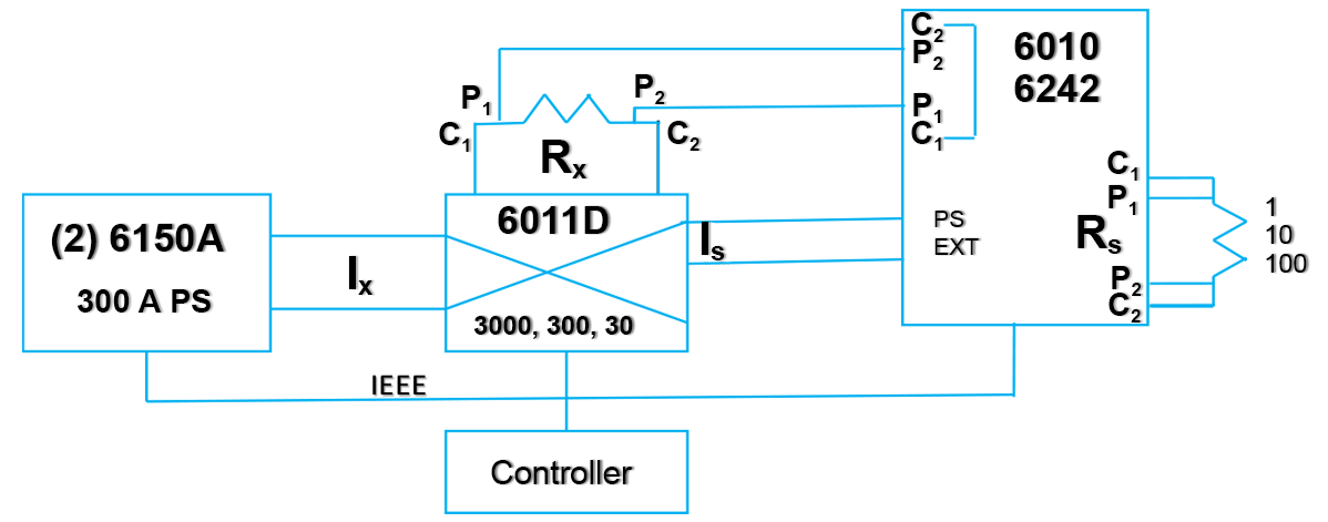
Figure 3: 6010/300 A Schematic
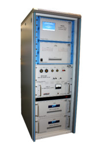
Figure 4: 6010/300 A System
You can also use standard resistors of 1 Ω, 10 Ω, and 100 Ω to extend the ratio of MI’s 6011 series of range extenders for higher currents. For example, if a 0.01 Ω shunt needed to be calibrated at 300 A, you could calibrate it on range 3000 using a 10 Ω standard on Rs. Similarly, you could calibrate a 0.1 Ω shunt at 15 A on range 3000 using a 100 Ω standard. Table 2 shows the system ratio uncertainty for the 6010/300 A or 6242/300 A systems. Lower uncertainties are available depending on the stability of your standards.
Table 2: 6010/6011/300 Ratio Uncertainty
| 6011/300 | 6010 | |||||||||||
| Rx | Test I | Range | Ratio | Ix | Range | Vrx | Unc² | Rs | Ratio | Irs | Vrs | Prs |
| Ω | A | A | S/M | A | % | V | ppm | Ω | M/S | A | V | W |
| 0.1 | 3 | 3 | 30 | 0.1 | 100 | 0.3 | 0.2 | 1 | 1 | 0.1 | 0.3 | 0.01 |
| 0.1 | 0.3 | 3 | 30 | 0.01 | 10 | 0.03 | 0.3 | 1 | 1 | 0.01 | 0.03 | 0.0001 |
| 0.01 | 30 | 30 | 300 | 0.1 | 100 | 0.3 | 0.2 | 1 | 1 | 0.1 | 0.3 | 0.01 |
| 0.01 | 3 | 30 | 300 | 0.01 | 10 | 0.03 | 0.3 | 1 | 1 | 0.01 | 0.03 | 0.0001 |
| 0.001 | 300 | 300 | 3000 | 0.1 | 100 | 0.3 | 0.2 | 1 | 1 | 0.1 | 0.3 | 0.01 |
| 0.001 | 30 | 300 | 3000 | 0.01 | 10 | 0.03 | 0.3 | 1 | 1 | 0.01 | 0.03 | 0.0001 |
| 0.0001 | 300 | 300 | 3000 | 0.1 | 100 | 0.03 | 0.3 | 1 | 1 | 0.1 | 0.03 | 0.01 |
| 0.0001 | 30 | 300 | 3000 | 0.01 | 10 | 0.003 | 0.4 | 1 | 1 | 0.01 | 0.003 | 0.0001 |
| 0.00001 | 300 | 300 | 3000 | 0.1 | 100 | 0.003 | 2 | 1 | 1 | 0.1 | 0.003 | 0.01 |
| 0.00001 | 30 | 300 | 3000 | 0.01 | 10 | 0.0003 | 3 | 1 | 1 | 0.01 | 0.0003 | 0.0001 |
Note 2. Includes the uncertainty of the 6011 range extender and the 6010D or 6242D bridge and RSS with the standard deviation of the measurement (2 sigma)
System Power
The 6010/300 or 6242/300 systems can be powered from a 100 V, 120 V, 220 V, or 240 V single-phase power supply. To enhance mobility, the systems are mounted on wheels.
The 6010/3000 A or 6242/3000 A systems may be used in conjunction with MI’s 6011D/150, 6012M, 6013M or 6014M High Current Range Extenders and MI’s 6023, 6024 or 6025 High Current Reversing Switches for measuring shunt resistances between 0.1 μΩ and 0.1 Ω. The 6011D/150 has ratios of 10, 100 and 1,000. The 6012M, 6013M or 6014M have a ratio of 1000:1. Combined, this totals a ratio of 1,000,000:1 with input currents up to 3000 A. The maximum output current of the 6012M or 6014M is 2 A, 0.4 A, and 3 A, respectively. The output current of the 6012M feeds into the 6011D 10 A range and the 6014M on the 10 A range on the 6011D/150. Figure 5 shows the basic 6010/3000 A Shunt Calibration System schematic and Figure 6 provides a front view of the system.
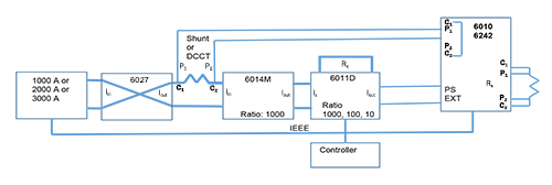
Figure 5: 6010/3000 A Shunt Calibration System schematic
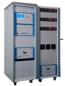
Figure 6: 6010/3000 A Shunt Calibration System with Optional 4220/30 A Scanner
The system is supplied in two 1530 mm height racks on wheels. The 6010/1000 includes the 6010/150 in one rack, and the 6014M and 6027 and one 1000 A power supply in the second rack. The 6010/2000 includes the 6010/150 in one rack, and the 6014M and 6027 and two 1000 A power supplies in the second rack. The 6010/3000 includes the 6010/150 in one rack, and the 6014M and 6027 and three 1000 A power supplies in the second rack.
The base accuracy for the 6010/3000 or 6242/3000 is < 2 ppm. This includes the uncertainty for the high current range extender (6014M), the 6011D/150 (1000, 100, 10), and the 6010 or 6242. Being a true ratio device, the power supplies or reversing switch has an insignificant contribution to the overall uncertainty of the system. Similarly, a ratio calibration technique is used to calibrate the 6014M and 6011D/150 Range Extender against the 6010/6242 bridges (see Figure 5).
6010/1000 A/2000 A/3000 A Connections
The shunt is connected at the side of the rack where two copper plates extend through the side panel. This effectively removes any heat loss due to poor connections from using wires or cables to connect the shunt. In the high current shunt measurement system, the output current of the 6014 range extenders (with a ratio of 1000:1) feeds directly into the 6011/150 A Range Extender as automatic ranging is performed inside the 6011/150.
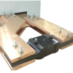
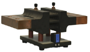
Figure 7: Shunt Connections
Figure 7 shows a 3000 A shunt connected to the 6010/3000 A terminals. Copper bars are used to extend the 6010/3000 A bus connections so that there is no heat loss in the connections or copper bars. This yields lower standard deviations in the measurements and is far superior to using cables. These copper bars can be supplied as an option with MI shunts.
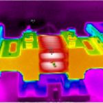
9332/3000 A Shunt/10 µΩ
Measurements International also manufactures a variety of shunts ranging from a 10 A (model 9332/10) to 3000 A (model 9332/3000/10 µΩ). These shunts are designed so that the current is evenly distributed across the plates. Figure 8 shows a 9332/3000 A shunt with a thermocouple under normal and thermal imaging. All MI high current shunts come with a thermocouple to measure the temperature of the shunt.
|
|
|
Table 3: 6010/6011/3000 Ratio Uncertainty
| 6011/3000 | 6010 | ||||||||||||
| Rx | Test I | Range | Ratio | O/P | Vrx | Prx | Unc | Rs | Ix | Ratio | Irs | Vrs | Prs |
| Ω | A | mA | V | W | ppm1,2 | Ω | mA | M/S | mA | V | W | ||
| 0.001 | 500 | 10,000 | 0.0001 | 50 | 0.5 | 250 | 0.2 | 1 | 50 | 1 | 50 | 0.5 | 0.0025 |
| 0.001 | 1000 | 10,000 | 0.0001 | 100 | 1 | 1000 | 0.2 | 1 | 100 | 1 | 100 | 0.1 | 0.01 |
| 0.0001 | 500 | 10,000 | 0.0001 | 50 | 0.05 | 25 | 0.3 | 1 | 50 | 1 | 50 | 0.5 | 0.0025 |
| 0.0001 | 1000 | 10,000 | 0.0001 | 100 | 0.1 | 100 | 0.3 | 1 | 100 | 1 | 100 | 0.1 | 0.01 |
| 0.00001 | 1000 | 100,000 | 0.00001 | 10 | 0.01 | 10 | 1 | 1 | 10 | 1 | 10 | 0.01 | 0.0001 |
| 0.00001 | 3000 | 100,000 | 0.00001 | 30 | 0.03 | 90 | 1 | 1 | 30 | 1 | 30 | 0.03 | 0.0009 |
| 0.000001 | 1000 | 1,000,000 | 0.000001 | 1 | 0.001 | 1 | 2 | 1 | 1 | 1 | 1 | 0.001 | 0.000001 |
| 0.000001 | 3000 | 1,000,000 | 0.000001 | 3 | 0.003 | 9 | 2 | 1 | 3 | 1 | 3 | 0.003 | 0.000009 |
| 0.0000001 | 3000 | 1,000,000 | 1,000,000 | 0.3 | 0.0003 | 0.9 | 2 | 0.1 | 0.3 | 1 | 1 | 0.0003 | 0.0000009 |
Note 1: See Table 1 for 6010/6011D-150 A specifications.
Note 2: As this is a ratio calibration, the uncertainties can be improved upon using the self-calibration technique of the extenders. Lower uncertainties are achievable depending on the stability of your standards.
Resistance-Temperature and Time-Temperature Curves (Optional)
All MI high current shunt measurement systems can provide both the resistance-temperature curve as well as the time-temperature curve for the shunt being measured—a feature only MI offers. This type of curve determines the characteristics of the shunt when the heat is dissipated by the shunt elements and is modelled by a second-order polynomial (see Chart 1). Equilibrium is obtained when the temperature and resistance of the shunt reach a steady state at the current level being measured. Once the resistance-temperature equilibrium curve has been established, the shape will not change; however, the resistance may drift over time, as does a typical resistance standard. The MI 6010/3000 software interfaces to a thermometer readout for shunt temperature measurements to ensure that the same temperature can be reached every time. Measuring the temperature of the shunt is particularly important when either cables or braided cables are used in connecting the shunt.
| Model Number | Current Maximum |
| 6010-150 A | 150 Amps |
| 6010-300 A | 300 Amps |
| 6010-400 A | 400 Amps |
| 6010-1000 A | 1000 Amps |
| 6010-2000 A | 2000 Amps |
| 6010-3000 A | 3000 Amps |
| 6242/150 A | 150 Amps |
| 6242/300 A | 300 Amps |
| 6242/400 A | 400 Amps |
| 6242/1000 A | 1000 Amps |
| 6242/2000 A | 2000 Amps |
| 6242/3000 A | 3000 Amps |
Accessories
To lower the uncertainties of the measurement, you can use the following MI accessories for the 6010/3000 or 6242/3000 systems: 9400 Oil Bath (see Figure 9), 9300A Air Bath (see Figure 10), 9210A & B Oil Resistors (see Figure 11), 9331R Air Resistors (see Figure 12), a complete set of 9332 Shunts (see Figure 13) and Shunt Extender Plates (see Figure 14). In addition, we can supply all necessary high- and low-current cables for connecting your shunts.
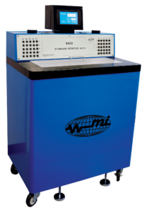
Figure 9: 9400 Oil Bath |
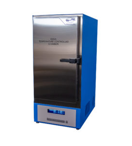
Figure 10: 9300A Air Bath |
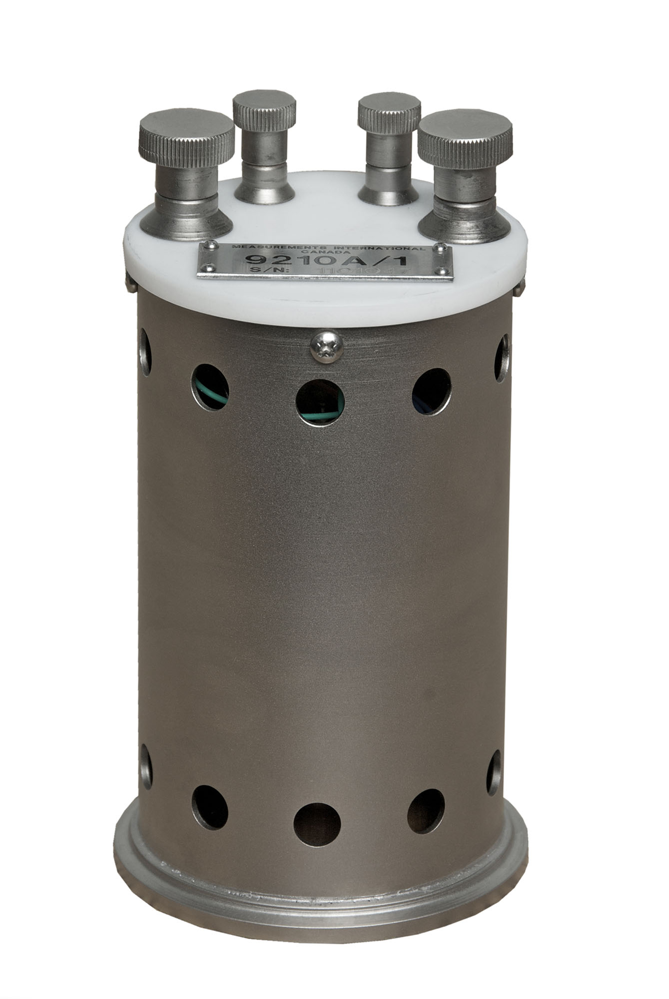
Figure 11: 9210A Oil Resistors |
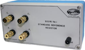
Figure 12: 9331R Air Resistor |
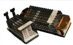
Figure 13: 9332 Shunts (10 A to 3000 A) |
Figure 14: Extender Plates |
| Specifications | |||
| Measurement Range | 150 mA to 150 A | 100 μΩ to 1 Ω | |
| 150 mA to 300 A | 10 μΩ to 1 Ω | ||
| 300 A to 3000 A | 1 μΩ to 1 Ω | ||
| Ratio Ranges | 1 to 1,000,000:1 | ||
| Linearity | ± 0.01 ppm of full-scale | ||
| Warm-Up Time to Full Rated Accuracy | 1 minute | ||
| Temperature Coefficient | 0.01 ppm/°C | ||
| Communication | IEEE-488 | ||
| Test Current Accuracy
Note: A 0.1 % current magnitude error is equal to 0.1 ppm in the ratio for supplies that use a reversing switch. |
150 mA to 150 A | ± 0.1 % | |
| 150 mA to 300 A | ± 0.1 % | ||
| 300 A to 3000 A | ± 0.1 % of range + 1-bit for 8 hours | ||
| Compliance Voltage | 0 to 150 A | 4.2 V | |
| 150 A to 3000 A | 10 V | ||
| Operating Temperature to Full Specification | |||
| Maximum Operating Range (30 to 90 % RH) | +10 °C to +40 °C | +50 °F to 104 °F | |
| Temperature Storage Range | -20 °C to +60 °C | -4 °F to +140 °F | |
1-800-324-4988
613-925-5934
Measurements International Ltd.
PB 2359, 118 Commerce Drive,
Prescott, Ontario, Canada K0E 1T0
© All Rights Reserved Measurements International