Featuring
The 1310B was designed to meet the requirements of automated DVM and calibrator calibration. Built around a low-thermal scanner, and temperature controlled enclosure the 1310B provides 11 high stability standard reference resistors ranging from 0.1 Ω to 1 GΩ, covering the full range of resistance standards required for precision calibration. The 0.1 Ω and 1 Ω standards are also capable of handling the majority of current levels needed for verifying current input and output on units under test (UUTs).
Additionally, the system includes two external channels that function as a connection hub for auxiliary AC and DC calibration equipment.
| Feature | Benefit |
| 11 resistors values ranging from 0.1 Ω up to 1 GΩ. | Complete line of decade value standards in one temperature-controlled enclosure. |
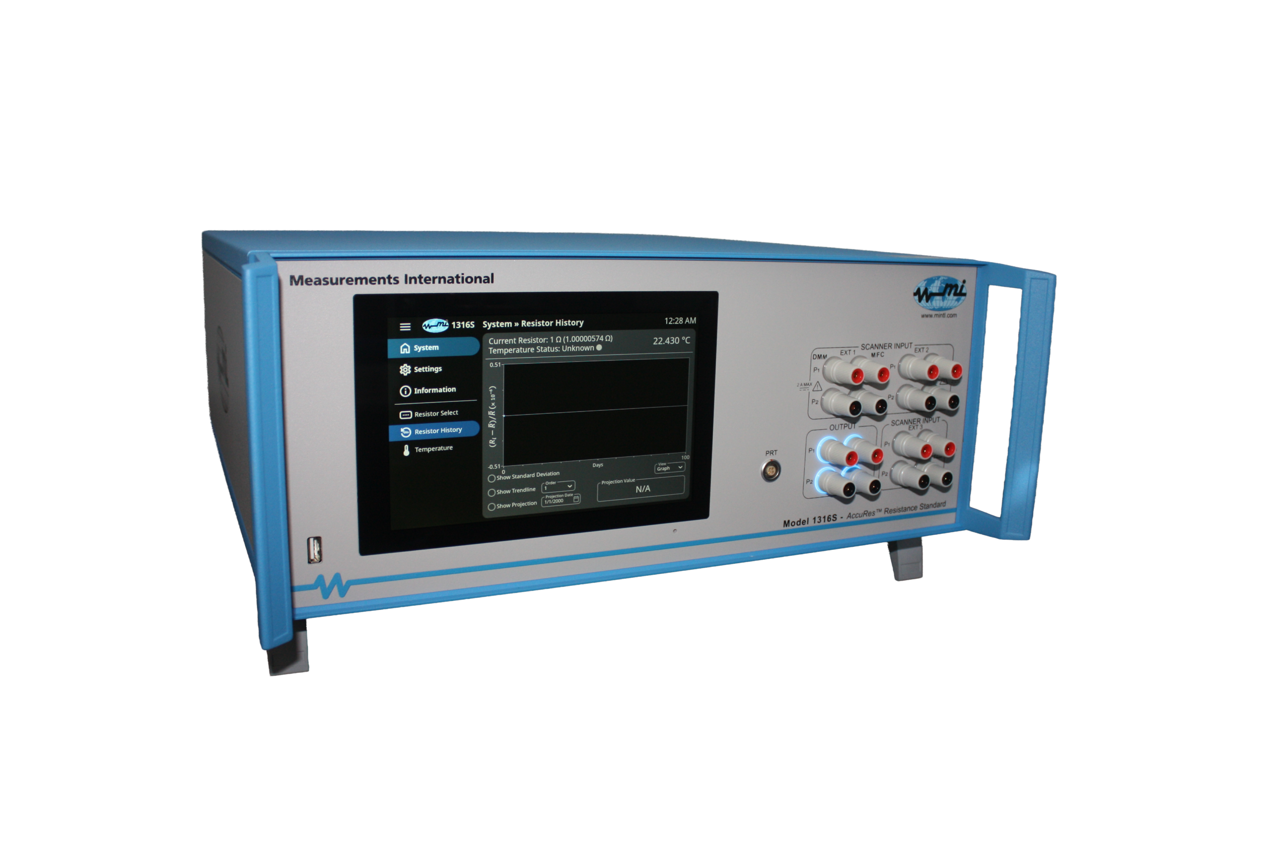
| User Friendly Touch Screen Interface. | Resistor Tracking and history graph. |
| Internal resistance elements in a temperature controlled chamber. |
Excellent stability and extremely low- temperature coefficients. |
| Single output cable for direct plug-in. | Easy operation without the requirement for changing wires. |
| Built for calibration of calibrators and DVMs. | Best stability < 2.5 μΩ/Ω/Year. |
| Built-in 4-terminal scanner. | Combining multiple instruments into one simple to use instrument (resistors, air bath, scanner). |
| Two external extra channels. | Connect to the resistance value of your choice. |
| Front panel or GPIB controlled. | Simplifies operation for the user. |
| Internally mounted temperature sensor PT100. | Users can connect to the front panel and monitor internal oven. |
| Nominal Resistance (ohms) |
Nominal Resistance (± µΩ/Ω) (± ppm) |
24 Hour Stability (± µΩ/Ω) (± ppm) |
12 Month Stability (± µΩ/Ω) (± ppm) |
Temperature Coefficient (± µΩ/Ω/°C) (± ppm/°C) |
Max. Voltage (Volts) |
| 1 G | 100 | 0.8 | 40 | 0.06 | 200 |
| 100 M | 50 | 0.4 | 10 | 0.025 | 200 |
| 10 M | 35 | 0.25 | 10 | 0.025 | 200 |
| 1 M | 25 | 0.03 | 2.5 | 0.02 | 200 |
| 100 k | 15 | 0.02 | 2.5 | 0.01 | 100 |
| 10 k | 10 | 0.01 | 2.5 | 0.005 | 32 |
| 1 k | 10 | 0.01 | 2.5 | 0.005 | 10 |
| 100 | 10 | 0.01 | 2.5 | 0.005 | 3.2 |
| 10 | 10 | 0.01 | 2.5 | 0.005 | 1.0 |
| 1 | 10 | 0.01 | 2.5 | 0.005 | 0.32 |
| 0.1 | 100 | 0.1 | 10* | 0.025 | 0.3 |
| Temperature Stability | ± 0.01 °C Over a 1 Year Period | ||||
| Ambient Temperature Range | 23 °C ± 5 °C | ||||
| Ambient Humidity Range | 20 to 50 % RH | ||||
| Warranty | Standard 1 Year Parts & Labour | ||||
* Stability specifications based on using the shunt as a standard resistor
** 0.1 Ω Power Coefficient < 1 µΩ/Ω
Scanner Specifications
| Operation | Four-Terminal |
| Error Contribution | < 20 Nanovolts |
| Contact Configuration | Relay – Two Coil Latching |
| Max Carrying/Switching Current | 4/2 Amps @ < 30 Volt (DC) |
| Maximum Working/Switching Voltage | 1000/220 Volts @ < 100 mA (DC) |
| Contact Resistance | < 0.05 Ω |
| Expected Relay Life | 108 Operations |
| Insulation Resistance | > 1012 Ω |
1-800-324-4988
613-925-5934
Measurements International Ltd.
PB 2359, 118 Commerce Drive,
Prescott, Ontario, Canada K0E 1T0
© All Rights Reserved Measurements International