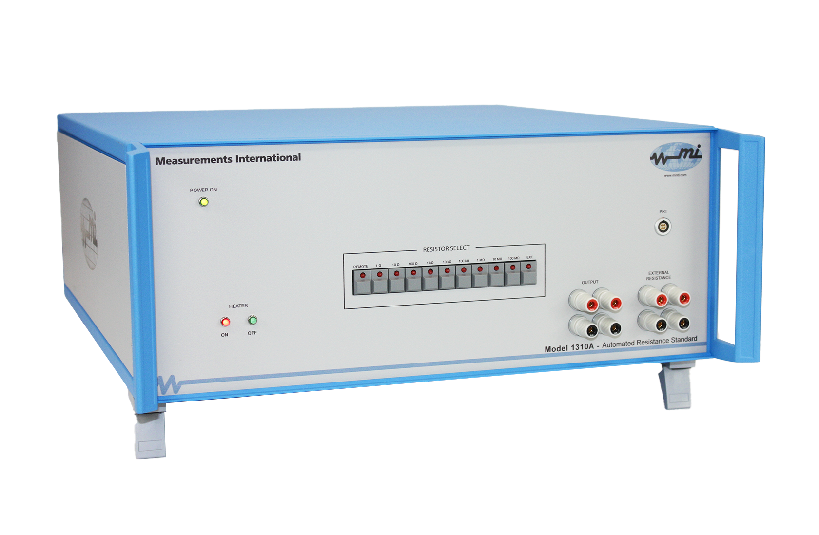
Developed and designed by metrologists for metrologists and calibration technicians
Transform your resistance standards calibration with MIs latest innovation: the 1310A Automated Resistance Standard. This user-friendly, cost-effective solution provides military organizations, national, and third-party labs with unparalleled accuracy and confidence in their resistance standards.
Designed with input from a world-renowned National Measurement Institute, the 1310A delivers exceptional results, making it the go-to choice for organizations looking to take their calibration to the next level. Upgrade your calibration process today, and trust in the precision and reliability of MI’s automated resistance standard.
| Feature | Benefit |
| 9 resistors (1 Ω, 10 Ω, 100 Ω, 1 kΩ, 10 kΩ, 100 kΩ, 1 MΩ, 10 MΩ, 100 MΩ), 1 external channel. | Complete line of decade value standards in one temperature-controlled enclosure. |
| Hand-picked high precision resistors in temperature-controlled chamber. |
Delivers highest level of performance from the internal high-precision resistors. |
| Internal resistance elements in a temperature-controlled chamber. | Excellent stability and extremely low-temperature coefficients. |
| Single output cable for direct plug-in. | Easy operation. No changing wires. |
| Built for calibration of calibrators and DVMs. | Best stability: < 2.5 μΩ/Ω/year. |
| Built-in 4-terminal scanner. | Combines two instruments into one. |
| External channel. | Connect to resistance value of your choice. |
| Front-panel or GPIB controlled. | Simplifies operation. |
| Internally-mounted temperature sensor PT100. | Connect to front panel to monitor internal oven. |
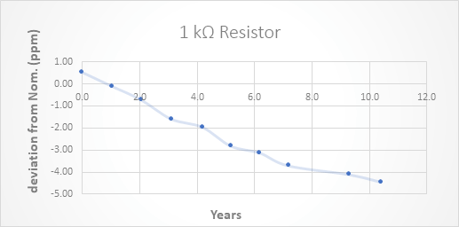
Figure 1. Drift of MI Resistor Over a 10 Year Period
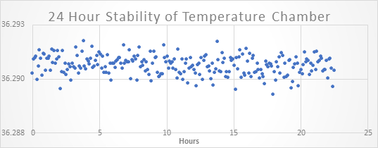
Figure 2. 24-Hour stability testing internal
temperature chamber
| Nominal Resistance (Ohms) |
Nominal Resistance (± μΩ/Ω) (± ppm) |
24 Hour Stability (± μΩ/Ω) (± ppm) |
12 Month Stability (± μΩ/Ω) (± ppm) |
Temperature Coefficient (± μΩ/Ω/°C) (± ppm/°C) |
Max. Voltage (Volts) |
|---|---|---|---|---|---|
| 100 MΩ | 50 | 0.4 | 10 | 0.025 | 100 |
| 10 MΩ | 35 | 0.25 | 10 | 0.025 | 100 |
| 1 MΩ | 25 | 0.03 | 2.5 | 0.02 | 100 |
| 100 kΩ | 15 | 0.02 | 2.5 | 0.01 | 100 |
| 10 kΩ | 10 | 0.01 | 2.5 | 0.005 | 32 |
| 1 kΩ | 10 | 0.01 | 2.5 | 0.005 | 10 |
| 100 Ω | 10 | 0.01 | 2.5 | 0.005 | 3.2 |
| 10 Ω | 10 | 0.01 | 2.5 | 0.005 | 1.0 |
| 1 Ω | 10 | 0.01 | 2.5 | 0.005 | 0.32 |
| Temperature Stability | ± 0.1 °C (one-year) | ||||
| Ambient Temperature Range | 23 °C ± 5 °C | ||||
| Ambient Humidity Range | 20% to 70% RH | ||||
| Warranty | 2 years (parts & labour) | ||||
Scanner Specifications
| Operation | 4-terminal |
| Error Contribution | < 20 nV |
| Contact Configuration | Two-coil latching relay |
| Max Carrying/Switching Current | 4/2 A @ < 30 V (DC) |
| Maximum Working/Switching Voltage | 200/20 Volts @ < 100 mA (DC) |
| Contact Resistance | < 0.05 Ω |
| Expected Relay Life | 108 operations |
| Insulation Resistance | > 1010 Ω @ 200 V |

1-800-324-4988
613-925-5934


Measurements International Ltd.
PB 2359, 118 Commerce Drive,
Prescott, Ontario, Canada K0E 1T0


© All Rights Reserved Measurements International