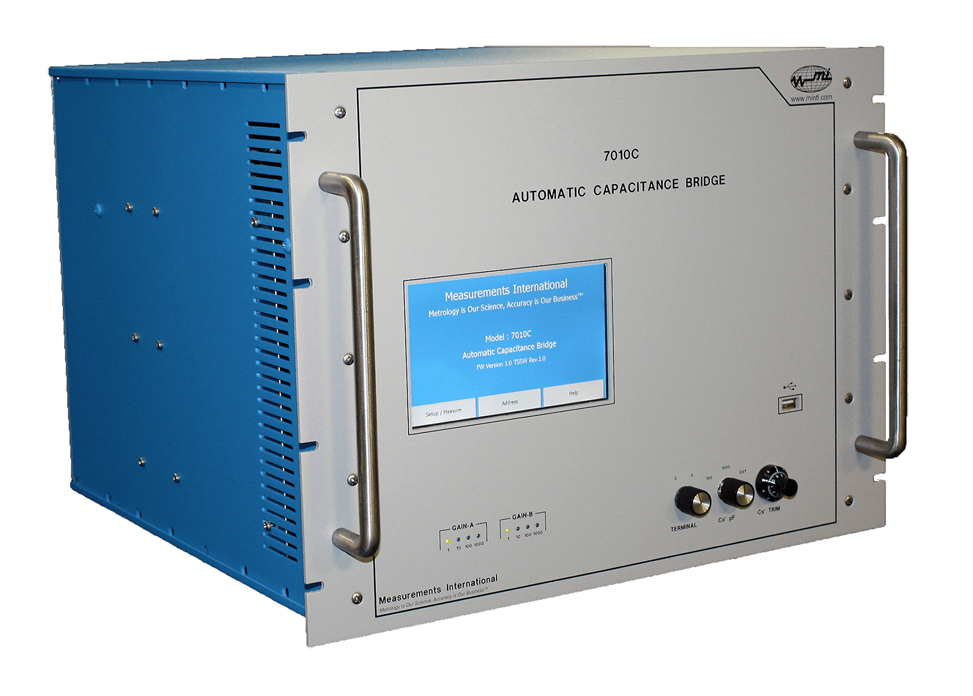
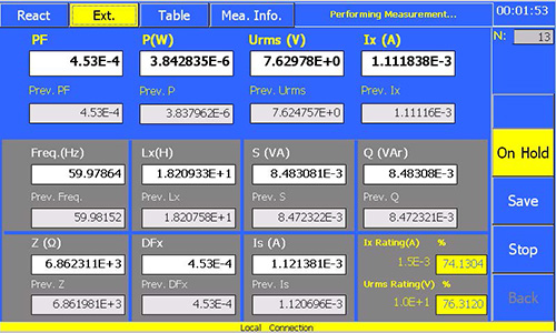
The 7010C is a microprocessor-controlled, current comparator–based automated capacitance bridge with metrology capabilities. It measures capacitance, inductance, reactor loss, and AC resistance, and also calibrates MI CTs. A large touchscreen displays relevant measuring quantities—capacitance (Cx), dissipation factor (Tan δ)—measured current through the standard capacitor, applied voltage, and frequency.
Operators configure measurements with the easy-to-use touchscreen menus, which includes the number of readings for statistical uncertainty analysis at the 95% (2σ) level. The touchscreen displays measurement data in table format. Before measurements start, users enter the reference capacitor (Cs) value through the touchscreen. All measured parameters transmit over the IEEE-488 interface for computer storage; a USB slot on the front panel also saves measurement parameters and data.
The 7010C achieves < 15 ppm accuracy in magnitude, and 1% of reading ± 10 ppm in dissipation across ratios from 1:1 to 1000:1. Dissipation spans 0 to 10% with 1 ppm resolution, making it ideal for both low- and high-voltage applications. A built-in lead compensation circuit reduces measurement lead length errors. An optional wheeled rack provides portability on the test floor.
The instrument measures inductance by automatically reversing the primary winding. The automatic self-balancing feature is a major advantage over manual capacitance bridges, as it facilitates accurate load loss measurements on large, high-voltage inductive loads. The 7010C also handles frequency changes by measuring frequency and updating the display.
To extend measurement ratios beyond 1000:1, the optional two-stage range extender model 7020 increases the ratio to 2,000,000:1. Transformer manufacturers use 7010C/7020 combinations with MI high-voltage capacitors to measure inductance and reactor losses in systems up to 600 kV.
Applications for the 7010C include:
Capacitance Measurement and Calibration
The 7010C is capable of performing both 2- and 3-terminal capacitance measurements. The 3-terminal measurements (with lead compensation) are typically used for large capacitors to remove lead impedance. The instrument operates with a standard capacitor (Cs) range of 10 pF to 10,000 pF, and a maximum measurement ratio of 1000:1. For higher capacitance ratios, the MI 7020 Range Extender extends the ratio to 2,000,000:1 . High-voltage standard capacitors (50 kV to 800 kV, 50–100 pF values) are available to support calibration work. The minimum applied voltage is 100 V when measuring a 1000 pF capacitor.
Voltage Transformer Calibration
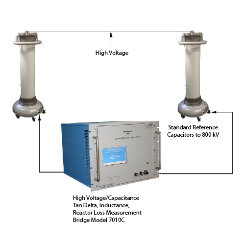
Voltage transformers calibrate using the 7010C and two high-voltage standard capacitors. First, measure the capacitor ratio at the voltage where the transformer will be tested. Apply the high-voltage supply to both the voltage transformer and the two standard capacitors. Interchange the capacitors during calibration; the voltage ratio calculates from the measurements, and the dissipation reading on the 7010C displays the transformer’s loss.
| Transformer Ratio |
Cs1 | Cs2 | Max Cs2 Volts | Bridge Ratio 1 |
Bridge Ratio 2 |
| 1 | 1000 pF | 1000 pF | 26 kV | 1 | 1 |
| 100 | 1000 pF | 1000 pF | 26 kV | 1 | 100 |
| 10 | 1000 pF | 100 pF | 260 kV | 10 | 1 |
| 1000 | 1000 pF | 100 pF | 260 kV | 10 | 100 |
| 100 | 5000 pF | 50 pF | 520 kV | 100 | 1 |
| 10000 | 5000 pF | 50 pF | 520 kV | 100 | 100 |
Note: The same specifications for accuracy of the 7010C Capacitance Bridge apply to each of the two measurements required for voltage transformers. Any voltage coefficient of the Cs1 and Cs2 capacitor should be taken into account when calculating the voltage ratio.
Inductance Measurement
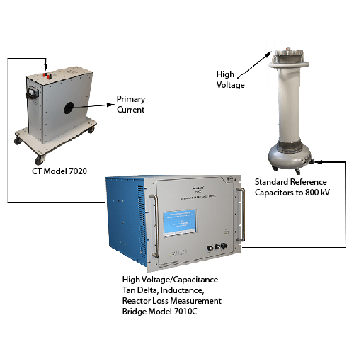
The capacitance bridge measures inductors by automatically reversing the primary winding. The reactive component of current, when reversed, comes into phase with the current through the standard capacitor, allowing a bridge balance with display readings in equivalent inductance ratio.
Note: Capacitance measurement accuracy is independent of supply frequency; inductance measurement accuracy depends on stable frequency. The 7010C automatically measures frequency and updates the display to compensate for changes.
The 7010C handles frequency changes by measuring the frequency and updating the display. Several transformer manufacturers use the MI 7010C, 7020, and High-Voltage Capacitor combination for measuring inductance and reactor losses, including systems as high as 600 kV. For inductance measurement, extend the 7010C’s range using the 7020 Two-Stage Compensated Current Transformer, which has a single ratio up to 2000:1; the combined 7010C and 7020 ratio is 2,000,000:1. See the inductance measurement range table for a complete range of inductance measurements.
| Capacitor Cs (pF) |
Max Voltage @ 50 Hz (V) |
Bridge Ratio |
Extender Ratio |
Max Inductance (H) |
Max Inductor Current (A) |
| 10000 | 3180 | 723 | 2 | 0.7 | 14.46 |
| 10000 | 3180 | 723 | 20 | 0.07 | 144.6 |
| 10000 | 3180 | 723 | 200 | 0.007 | 1446 |
| 10000 | 3180 | 723 | 2000 | 0.0007 | 14460 |
| 1000 | 31800 | 723 | 2 | 7 | 14.46 |
| 1000 | 31800 | 723 | 20 | 0.7 | 144.6 |
| 1000 | 31800 | 723 | 200 | 0.07 | 1446 |
| 1000 | 31800 | 723 | 2000 | 0.007 | 14460 |
| 100 | 318000 | 723 | 2 | 70 | 14.46 |
| 100 | 318000 | 723 | 20 | 7 | 144.6 |
| 100 | 318000 | 723 | 200 | 0.7 | 1446 |
| 100 | 318000 | 723 | 2000 | 0.07 | 14460 |
| 50 | 636000 | 723 | 2 | 140 | 14.46 |
| 50 | 636000 | 723 | 20 | 14 | 144.6 |
| 50 | 636000 | 723 | 200 | 1.4 | 1446 |
| 50 | 636000 | 723 | 2000 | 0.14 | 14460 |
| Capacitor Cs (pF) |
Max Voltage @ 60 Hz (V) |
Bridge Ratio |
Extender Ratio |
Max Inductance (H) |
Max Inductor Current (A) |
| 10000 | 2650 | 1005 | 1 | 0.7 | 10.04 |
| 10000 | 2650 | 1005 | 10 | 0.07 | 100.4 |
| 10000 | 2650 | 1005 | 100 | 0.007 | 1004 |
| 10000 | 2650 | 1005 | 1000 | 0.0007 | 10041 |
| 1000 | 26500 | 1005 | 1 | 7 | 10.04 |
| 1000 | 26500 | 1005 | 10 | 0.7 | 100.4 |
| 1000 | 26500 | 1005 | 100 | 0.07 | 1004 |
| 1000 | 26500 | 1005 | 1000 | 0.007 | 10041 |
| 1000 | 26500 | 1005 | 2000 | 0.0035 | 20083 |
| 100 | 265000 | 1005 | 1 | 70 | 10.04 |
| 100 | 265000 | 1005 | 10 | 7 | 100.4 |
| 100 | 265000 | 1005 | 100 | 0.7 | 1004 |
| 100 | 265000 | 1005 | 1000 | 0.07 | 10041 |
| 100 | 265000 | 1005 | 2000 | 0.035 | 20083 |
| 50 | 530000 | 1005 | 1 | 140 | 10.04 |
| 50 | 530000 | 1005 | 10 | 14 | 100.4 |
| 50 | 530000 | 1005 | 100 | 1.4 | 1004 |
Note: If other Inductance Measurement Ranges are required, contact Measurements International
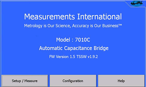
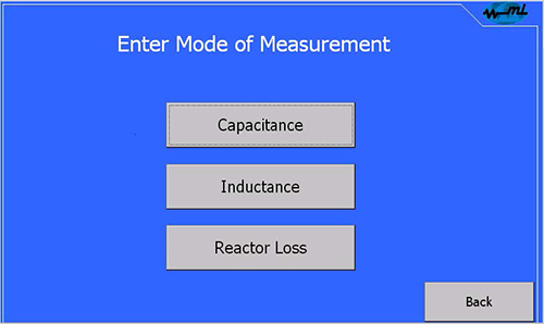
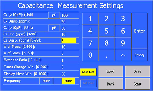
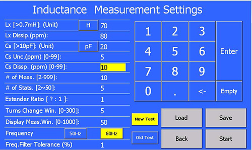
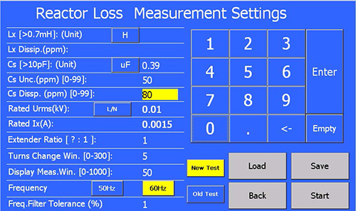
Turning on the 7010C power switch automatically loads the program and performs initialization routines, including A/D converter calibration. The touch screen provides full operational control of capacitance, inductance, and reactor loss measurements.
For each measurement type, the system prompts users to enter parameter settings on a dedicated setup page:
| Capacitance Range | Cs: 10 pF to 10,000 pF Cx: 10 pF to 10,000,000 pF (10 µF) |
| Capacitive Ratio 1:1 to 1000:1 | Ns: 0 to 1.11110 in steps of 0.000001 Nx: 1 to 1000 in steps of 1, 2, 5 |
| Primary Current (A) | 10 (maximum) |
| Secondary (Cs) Current Range | 40 µA to 10 mA |
| Dissipation Factor Range | 0 to 10 % in steps of 0.000001 |
| Inductance Range | 700 µH to 700,000 H (Q factor > 10) |
| Test Frequencies | 50 Hz and 60 Hz |
| Accuracy | Ratio: ± 15 ppm for all Cx ratios |
| Loss Angle | ± 1 % of reading ± 10 ppm |
| Screen Display | 7-inch |
| Warm-Up Time | < 5 minutes to full rated accuracy |
| Operating Environment | 18°C to 34°C, 10% to 80% RH |
| Operating Power | 100, 120, 220, 240 V | 50/60 Hz |

1-800-324-4988
613-925-5934


Measurements International Ltd.
PB 2359, 118 Commerce Drive,
Prescott, Ontario, Canada K0E 1T0


© All Rights Reserved Measurements International