




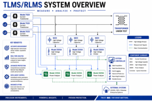
The AccuLoss® Transformer Loss Measurement System (TLMS) and Reactor Loss Measurement Systems (RLMS) from Measurements International Limited are metrology-grade solutions designed for precise transformer and reactor loss measurements. Engineered for modern, high-voltage testing, these systems deliver industry-leading accuracy, even under challenging conditions, like extremely low power factor measurements (PF = 0.001).
Using precision voltage dividers and advanced simultaneous sampling wattmeter technology, TLMS and RLMS provide fast, stable, and highly repeatable results, making them well suited for both production and laboratory environments.
Built on proven metrology principles, the system is simple to calibrate using traceable reference standards. This reduces complexity and downtime while ensuring long-term confidence in measurement accuracy. The modular and scalable architecture supports configurations up to 800 kV and 6000 A, enabling seamless integration into new or existing test facilities across a wide range of applications.
The system supports a comprehensive range of testing applications, including load and no-load loss measurements, heat run testing, induced voltage testing, and reactor calibration at very low power factors. Integrated software provides automated test sequences, waveform analysis, and flexible data output, improving efficiency while maintaining consistent, high-quality results.
Optional oil-filled current transformers (CTs), including electronically aided and compensated designs, further extend system capability—allowing a single platform to support both transformer and reactor testing with high accuracy and stability.
The AccuLoss® System is designed to test small, medium, and large power transformers, up to 400 Hz, ideal for R & D facilities.
The AccuLoss® System also calibrates single- and 3-phase reactors at power factors < 0.001.
| Feature | Benefit |
| Industry-Leading Measurement Accuracy | Ensures confidence in results, even at PF = 0.001, supporting compliance with global standards and improving product quality. |
| Simultaneous Sampling Technology | Eliminates phase errors and delivers fast, stable, and highly repeatable measurements. |
| Scalable to 6000 A / 800 kV | Supports testing from distribution to ultra-high-voltage transformers within a single platform. |
| Modular System Architecture | Enables easy upgrades and integration into existing facilities, protecting long-term investment. |
| Flexible Test Configurations | Accommodates horizontal and vertical bushings, and a wide range of transformer designs. |
| Optimized for Low Power Factor | Maintains high accuracy under the most challenging measurement conditions. |
| Supports Energy-Efficient Design | Helps manufacturers reduce transformer losses and meet efficiency requirements. |
| Environmentally Responsible Design | Contributes to reduced emissions, and supports ESG and sustainability initiatives. |
| Model Series | Maximum Current | Voltage Capability |
| 2100 – 2300 | Up to 2 kA | Up to 300 kV |
| 3100 – 3300 | Up to 3 kA | Up to 300 kV |
| 4100 – 4300 | Up to 4 kA | Up to 300 kV |
| Model Series | Maximum Current | Voltage Capability |
| 2300 – 2800 | Up to 2 kA | 300 – 800 kV |
| 4300 – 4800 | Up to 4 kA | 300 – 800 kV |
| 6300 – 6800 | Up to 6 kA | 300 – 800 kV |
Optional oil-filled current transformers (CTs) are available, including electronically aided and compensated designs. These configurations extend measurement capability, and allow a single system to support both transformer and reactor testing, providing a flexible, high-performance solution across a wide range of applications. Contact MI for Details
| Power Factor | Range | Accuracy |
| cos φ = 1.000 | ≥ 100 V ≥ 1 A | 0.03 % |
| cos φ = 0.100 | ≥ 100 V ≥ 1 A | 0.04 % |
| cos φ = 0.050 | ≥ 100 V ≥ 1 A | 0.06 % |
| cos φ = 0.020 | ≥ 100 V ≥ 1 A | 0.13 % |
| cos φ = 0.010 | ≥ 100 V ≥ 1 A | 0.27 % |
| cos φ = 0.005 | ≥ 100 V ≥ 1 A | 0.54 % |
| cos φ = 0.001 | ≥ 100 V ≥ 1 A | 2.74% |
| HV Bushing Style | Horizontal | Vertical | ||||
| Voltage | ||||||
| Applied Voltage
(Line to Neutral) |
100 V to 100 kV | 100 V to 100 kV | 100 V to 200 kV | 100 V to 300 kV | ||
| Accuracy | ≤ 0.05 % of full scale | |||||
| Current | ||||||
| Applied Current (A) | 1 to 2000 | 1 to 4000 | 1 to 6000 | 1 to 4000 | 1 to 6000 | 1 to 4000 |
| Input Current Ratio | 2000:1 | 2000:1 | ||||
| Accuracy | ≤ 0.005 % of full scale | |||||
| Ranges, A
(Blue – Premium)
Note: All CT’s are protected against power outages. |
10
20 40 100 200 400 1000 2000
|
10
20 40 100 200 400 1000 4000
|
10
20 40 100 200 400 1000 6000
|
10
20 40 100 200 400 1000 4000
|
10
20 40 100 200 400 1000 6000
|
10
20 40 100 200 400 1000 4000
|
| Power | ||||||
| Power Factor | 1, 0.1, 0.05, 0.02, 0.01, 0.005, 0.002, 0.001 | |||||
| Accuracy | ≤ 0.05 % to ≤ 1.21 % | |||||
| Safety Clearances | ||||||
| To Adjacent Walls | 1.3 m | 2.6 m : 3.9 m for 300 kV | ||||
| Between Phase | 1.3 m | 2.6 m : 3.9 m for 300 kV | ||||
| Power Supply | ||||||
| Voltage | 100, 120, 220, 240 V ± 10 % | |||||
| Frequency | 50/60 Hz | |||||
| Power | 1200 VA | |||||
| Environmental Conditions | ||||||
| Operating Temperature | Control Cabinet: 15 °C to 30 °C, Bushings and Capacitors: 0 °C to 40 °C | |||||
| Storage Temperature | – 20 °C to 50 °C | |||||
| Relative Humidity | 30 % to 90 % (non condensing) | |||||

1-800-324-4988
613-925-5934


Measurements International Ltd.
PB 2359, 118 Commerce Drive,
Prescott, Ontario, Canada K0E 1T0


© All Rights Reserved Measurements International

