Simplify Your Procedures. Simplify Your Work.
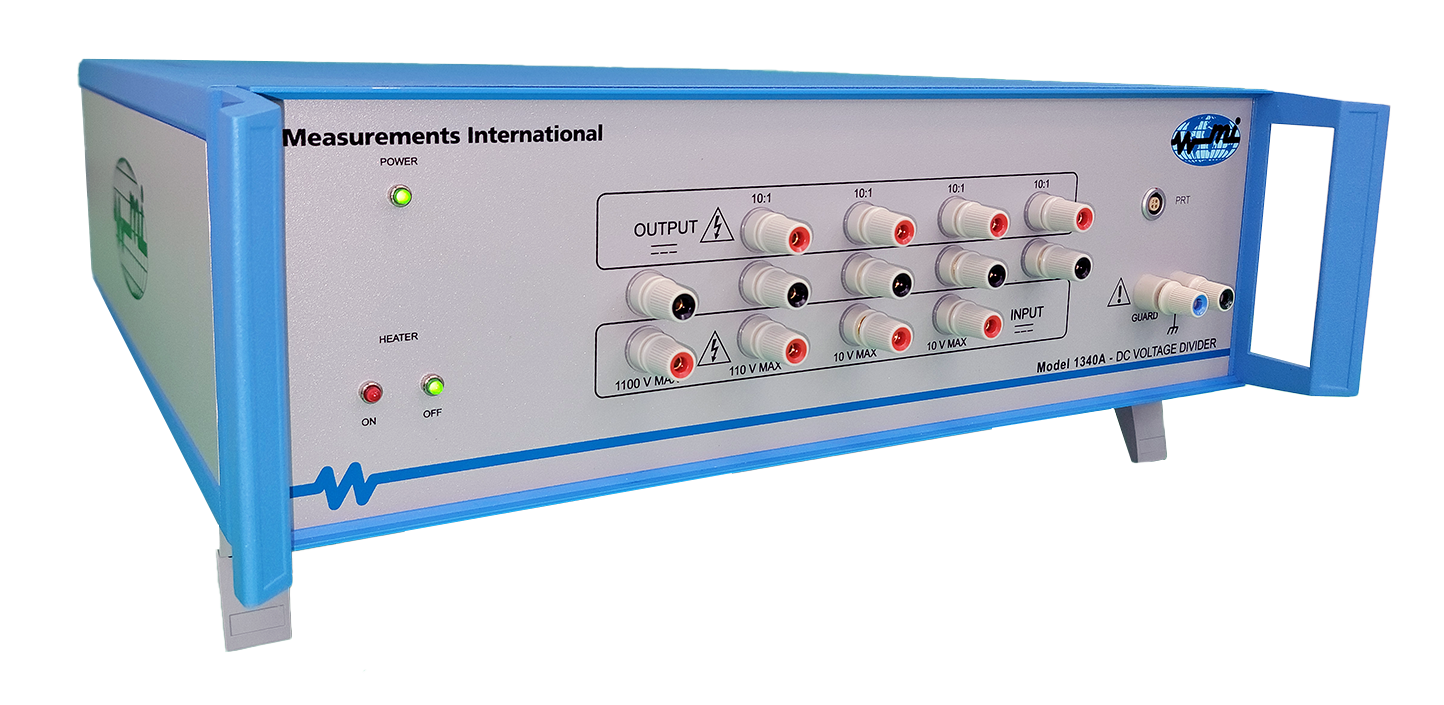
Never before has DC voltage calibration and/or verification of DVMs and calibrators been so easy or reliable. Measurements International’s recently launched 1340A High Precision Voltage Divider is the metrology industry’s leading choice thanks to its user friendly design, backed with the best features for optimal performance. Model 1340A is another fine example of MI’s history and world-leading experience and product line in voltage (see here). We invite Metrologists and calibration technicians in national, military and third-party calibration laboratories to compare the performance of the 1340A against any products on the market today.
| Feature | Benefit |
| 10:1, 100:1, and 1000:1 reference divider output to 1100 V. Accuracy divides input voltage by 10, 100, 1000, or 10000. Maximum input voltage is 1100 V. | Extreme precision to compare direct voltage levels of various sources to a 10 V voltage reference standard like a 1330A, 732B or 732C. |
| Industry-leading specifications requires no Self-Alignment or Calibration prior to use. | Customers no longer need to self-align or calibrate prior to each use. Saves time and money and frustration! |
| Utilizes a special design network of high precision resistors mounted in a temperature-controlled chamber. | Shields divider resistors from outside noise and provides temperature stability to improve performance. |
| Front panel direct connection to calibrator; divider output connection to DVM for testing; both done with supplied cables. | Ease of use, saves time and money. |
| Internally mounted temperature sensor PT100. | Users can connect to front panel and monitor internal oven. |
| New special hand-selected resistors and configuration. | Lengthy, self-alignment no longer required to create divider network. |
| Calibration of divider performed directly against a 1330A, 732B or 732C reference. | Industry-leading advancement in the DC voltage divider commercial products which delivers exceptional performance. |
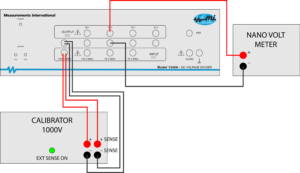
Figure 1. Example: 1000 V in divided to 10 V out to be measured
An intuitive and easy to use instrument
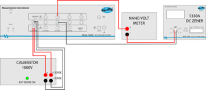
Figure 2. The above diagram illustrates using a 1330A, 732B or 732C reference in the connection sequence. A DVM can be used as a NULL detector to determine the offset of the 57XX series on the 10:1 and 100:1 ratio.
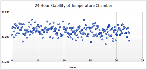
Figure 3. 24 Hour Stability of Temperature Chamber
| Ratio Range | Uncertainty / 30 Days | Input Voltage (V) | |||
|---|---|---|---|---|---|
| 7 Day | 30 Day | 90 Day | 1 Year | ||
| Stage 1 10:1 | 0.04 | 0.2 | 0.5 | 2.0 | 10 V |
| Stage 2 10:1 | 0.04 | 0.2 | 0.5 | 2.0 | 10 V |
| Stage 3 10:1 | 0.04 | 0.2 | 0.5 | 2.0 | 110 V |
| Stage 4 10:1 | 0.04 | 0.2 | 0.5 | 2.0 | 1100 V |
| 100:1 | 0.1 | 0.3 | 1.0 | 3.0 | |
| 1000:1 | 0.1 | 0.3 | 1.0 | 3.0 | |
| 10000:1 | 0.1 | 0.4 | 1.o | 4.0 | |
| Internal Temperature Stability | ± 0.1°C Over a 1 Year Period | ||||
| Ambient Temperature Range | 23 °C ± 5 °C | ||||
| Initial Warm-up Time | 24 Hours | ||||
| Ambient Humidity Range | 20 % to 90 % Non-condensing | ||||
| Storage | -50 °C to +50 °C | ||||
| Alignment | Not Required | ||||
| Isolation to Earth | > 1012 Ω | ||||
| Direct Cable to 57XX | Provided | ||||
| PT 100 Cable | Provided | ||||
| Warranty | Standard 2 Year Parts & Labour | ||||
1-800-324-4988
613-925-5934
Measurements International Ltd.
PB 2359, 118 Commerce Drive,
Prescott, Ontario, Canada K0E 1T0
© All Rights Reserved Measurements International