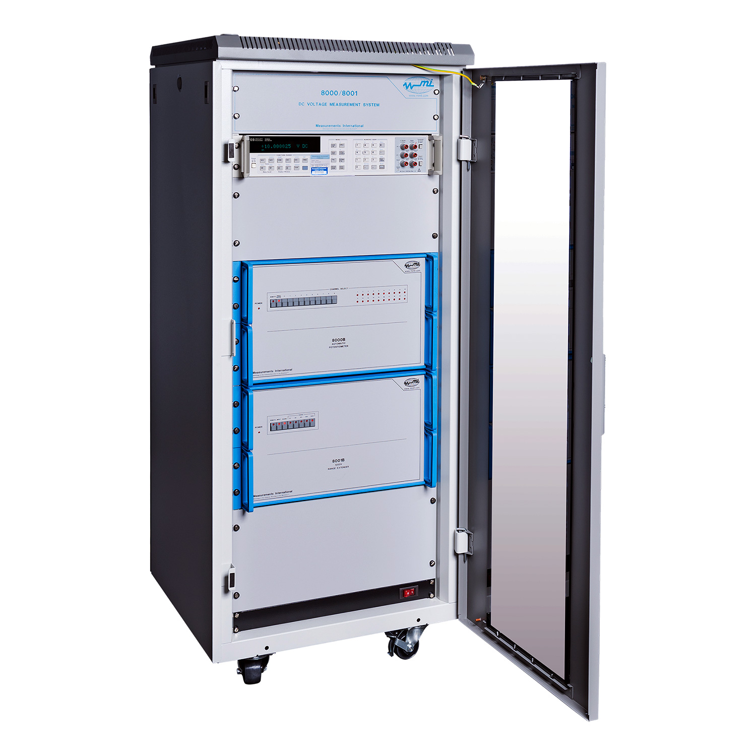
The Automated Voltage Divider System is a highly versatile, accurate, self-balancing ratio instrument that meets laboratory requirements for scaling between a Josephson-calibrated 10 V reference and any voltage between 1 mV to 1200 V. Automatic self-calibration ensures ratios to nine significant digits with linearity deviations of < 0.02 ppm. The Automated Voltage Divider System consists of the MI model 8000B Binary Voltage Divider with a voltage range from 1 mV to 10 V and the model 8001B with a range from 10 V to 1200 V. A 10 V source, a detector and a 10 V reference for traceability completes the system. The model 8000B with its “built-in” 20-channel scanner can be used to measure up to twenty 10 voltage references automatically. The model 8001B has 5 input ranges. Both units are controlled via the MI 8000B operating software for performing automatic measurements.
Feature | Benefit |
Automated self-calibration. | Does not require sending out for calibration. |
Bipolar voltage measurements. | Allows for automatic + and – voltage measurements against + 10 V reference. |
Built-in 20-channel scanner. | Allows for automation of multiple UUT’s without connection changes to minimize thermal effects. |
Standard cell protection. | Protects references against accidentally shorting or loading. |
Calibration of 57XXA. | Automated characterization of Fluke 5700A/5720A/5703A voltage output. |
Calibration of DMM’s. | Can characterize the Voltage Linearity of Reference Multimeters like 3458A and 85X8A. |
1 mV to 1200 V DC range. | Enough range to calibrate all voltage calibrators without reconfiguring connections. |
Voltage maintenance. | Ideally suited to calibrate and intercompare 10 V Zener references. |
Low uncertainties. | 8000B – 0.05 × 10⁻⁶ for 10 V vs. 10 V measurements. 8001B – 1 × 10⁻⁶ for up to 1200 V. |
The Automated DC Voltage Measurement System was developed to address the increasing demand for automated calibration of the DC voltage function on precision multifunction calibrators and DVMs, as well as verifying the linearity verification of the long scale DVM’s. This allows the user to perform measurements up to ± 10 V with the 8000B and extend it to ± 1200 V when the 8001B extender is used.
The fully documented calibration of bipolar voltages at the output of the calibrator is traceable to the laboratory’s 10 V reference standard.
The 25-bit voltage divider is entirely passive. It consists of an improved 13-bit self-checking Cutkosky divider terminated by an 8 ½ digit DVM. Thus the higher-order Cutkosky divider provides the composite divider with the requisite accuracy, while the 8 ½ digit DVM extends its resolution without increasing its output resistance. Switching is effected by latching relays, simply controlled and monitored by a microprocessor which also interfaces to the IEEE-488 bus. The two main system operations, auto-calibration and auto-balancing ratio measurement, are designed to be software-driven by the desktop computer.
This makes an extremely versatile system that may be tailored for the experimental investigation of systematic errors as well as for other customized applications. The BVD requires a 10 Volt source, a DVM detector and a voltage reference. The source, a low drift, stable, noise-free signal, is connected to the rear input on the 8000B. The most important aspect of the source is its stability. Reference to the BVD is supplied from a calibrated stable 10 V reference. The source and 8000B are standardized against the calibrated reference for making absolute voltage measurements. The 8000B software automatically tracks the drift of the 10 V reference, whether a 1330A, 732B or 732C is used so that the reference value is always up to date. See the 8000B block diagram.
The DVM detector with an input impedance of 10 GΩ or higher is used to measure the difference between the output of the BVD and the voltage under test. An isolated guard circuit is provided to guard the BVD and the DVM detector when performing measurements. The guard voltage can also be used to drive the guards of the cell enclosures under test to reduce leakage problems.
Figure 1. 8000B Block Diagram
Figure 2. RVB
The model 8000B ratio can be verified by measuring the normal and inverse ratio of two stable resistors using the 8000B Ratio Verification Box (RVB) shown in Figure 2. The RVB contains two high-stability resistors, a low-thermal reversing switch and wiring so that the 8000B can be verified within its linearity specification. The program is built into the software and all measurements and data are stored in the measurement file. The software also performs the calculations of the ratio of the two resistors and the error of the bridge.
Figure 3. Model 8001B
The model 8001B Range Extender extends the measurement range of the model 8000B BVD to 1200 V. All voltages are calibrated directly against the 10 V reference on the 8000B. The 8001B includes ranges of 10, 30, 120, 300 and 1200 Volts. The 8001B maintains excellent short-term drift and is self-calibrating using the 8000B BVD. The combination of the two models can be used to calibrate and verify the linearity of both calibrators, DVM’s and Volt ratio boxes up to 1200 V.
The 8000B system is a practical solution to cover several measurements in voltage metrology. The applications that are covered are as follows.
1. Voltage Reference Calibration
The voltage maintenance can be easily carried out by connecting up to 20 reference Zeners to the built-in scanner of the 8000B system. The system can measure any voltage including the commonly used 10 V, 7 V, 1.018 V, and 1 V references.
Figure 4 shows the back panel of the unit, where one can identify the scanner, the source and the detector connectors.
Figure 4. BVD Back Panel
The number of devices under test (DUT) can be further increased by an extra 40 channels with one of the MI Matrix Scanner (model 4240A, 4220A, 4210A).
Our software allows easy definition of the measurement tasks to calibrate banks of Zener reference standards.
2. DC Voltage Calibrator for Multi-functional Calibrator
The 8000B enables a complete calibration of the multifunctional calibrator and DMMs (Figure 5). Connecting the 8001B to the 8000B the measurement range is extended up to 1200 V. The bootstrap method guarantees traceability to all ranges, moreover this method provides the best accuracy.
Figure 5. Calibrator and DVM
3. Calibration of Volt Ratio Dividers
The 8000B and 8001B combinations are ideal for calibrating Kelvin Varley dividers and other Volt ratio boxes. The 8000B has a Vh and Vl output for supplying 10 V directly to the Kelvin Varley divider. As an option, Volt ratio boxes can be calibrated at full-scale using the 8001B and a calibrator. The output from the Kelvin Varley divider or Volt ratio box is fed directly into one of the 20-channel scanner inputs that are available.
4. Calibration and Linearity of DVM
The pole reversal and the arbitrary selection of test voltages make the 8000B system the practical instrument to calibrate DVMs. The numerous measurement options are fulfilling the EURAMET CG-15 for calibration of DVM and can even extend these requirements. An example of a linearity test is shown in Figure 6.
Figure 6. DVM Linearity Check
Measurement International’s model 8000B software has been developed by metrologists for metrologists. It features “real-time” uncertainty analysis and graphing of measurement data (Figure 7). It provides single measurement and total ratios and its uncertainty.
The full system is configurable, to allow the multi-instrumentation connection (via IEEE-488.2). The user can choose among some of the most common calibrators and DVMs, such as Fluke 5720 and Keysight 3458A, however, a user-friendly interface allows the creation of other instrument drivers (Figure 8). Additionally, it is possible to configure the sources needed for measurements.
The program selection window provides all the information to create custom measurements. Several parameters are available to tune to user requirements. The simple drag-and-drop interface helps in the creation of programs to automate long measurement sessions.
The measurement results can be saved for historical and regression analysis. They can be exported to spreadsheet format to quickly report generation.
The software also provides a built-in algorithm to calibrate the 8000B and the 8001B models as shown in Figure 9. The calibration results are automatically used to correct the DUTs measurement. The saved calibration is brought back and displayed with a click of a button. Beside the correction factors and other information, the time stamp is shown.
System Requirements
To run the MI software (model 8000 SW) requires a computer running Windows 7 or later and USB to IEEE-488 interface (not included). Graphing, history logging, and data storage with export to Excel and regression analysis are provided.
Figure 7. Voltage Measurement
Figure 8. System and Rack Settings
Figure 9. 8000 and 8001 Calibration
8000B | 8001B | |||||
Automatic Self-Calibration | Completely Self-Checking | Completely Self-Checking | ||||
Ranges | 1 mV to 10 V (Single Continuous) | 30 V, 120 V, 300 V, 1200 V | ||||
Accuracy
K=2
|
|
|
||||
Insulation Resistance | > 1011 Ω | > 1011 Ω | ||||
Effective Linearity | < 0.02 ppm of Full-Scale (Full-scale 1 V, 10 V) |
< 0.02 ppm of Full-Scale | ||||
Long-Term Drift | N/A – Corrected by Self-Calibration |
N/A – Corrected by Self-Calibration |
||||
Short-Term Drift | Dependant on Drift of Source and Environmental Conditions | Dependant on Drift of Source and Environmental Conditions | ||||
Input Impedance | 40 kΩ | 4.8 MΩ Maximum | ||||
Output Impedance | 100 kΩ | 40 kΩ | ||||
Operating Environment | 18 to 34 °C, 10 to 80 % RH | 18 to 34 °C, 10 to 80 % RH | ||||
Storage Environment | -5 °C to 40 °C, 95 % Non-condensing |
-5 °C to 40 °C, 95 % Non-condensing |
||||
Warranty | 2 Years Parts & Labour | 2 Years Parts & Labour |